|
Week of ... |
Lab Topic(s) |
Reference
Material
[
this background indicates
required reading;
this background indicates
optional reading
this background indicates
important items
this foreground indicates updated
items
this background indicates
weekly topics
this foreground indicates unrevised
items
] |
|
Introduction
Integrated circuits
Pinouts, breadboards, and debugger boards
|
|
| Jan. 3 |
- Safety -
Emergency
Numbers
[
April 29, 2015
4.2K
]
-
Laboratory
Safety
-
Lab Introduction:
What is the purpose of the PC/CP220 labs?
[PDF]
[
April 29, 2015
187K
]
-
New Device:
Breadboards
[PDF]
[
May 1, 2012
14M
]
Breadboards
[HTML version]
[
May 12, 2017
7.1K
]
-
New Information:
Debugger boards
[PDF]
[
June 17, 2016
4.6M
]
Debugger Boards
[HTML]
[
May 12, 2017
8.7K
]
-
New Information:
Pinouts
[PDF]
[
April 12, 2011
194K
]
-
More Information:
Finding pin 1
[PDF]
[
May 23, 2014
2.1M
]
-
New Device:
Chip Pullers
[PDF]
[
February 11, 2014
7.4M
]
-
Lab:
Introduction to Digital Logic
[
September 18, 2017
9.4K
]
-
Next Lab is virtual: Do it on MyLearningSpace between
Tuesday and Thursday.
The lab time will be for help if you have problems.
Otherwise you don't need to attend the lab.
-
There is no quiz this week, but you could
use
the time to work ahead on next week's lab, since it is virtual
and may take a while.
|
|
N2083 Lab bench layout [video]

This has cool history on where the term "breadboard" came from
Basics of Breadboarding [video]

Collin's Lab: Schematics [video]

How to Wire Circuits from Schematics [video]

|
|
Maxima/Circuitverse introduction
Design skill: Testing logic with a computer
algebra system
Design skill: Circuit drawing and simulation
Instructions on MyLearningSpace
|
|
| Jan. 10 |
This week you'll learn how to use software to test logic.
-
New Tool:
Computer Algebra System
-
New Tool:
Digital Simulator
-
Lab:
Maxima and Circuitverse Introduction
-
Before next lab: Read documents (or watch videos) about
LEDs
and
prototype switches
and then do the quiz on
MyLearningSpace.
The quiz will be available from Friday at 7 a.m. until
Sunday
at 11:30 p.m. It will not be available
the day of your lab, so you
must do it ahead of time.
|
|
|
|
|
Resistors (including arrays), LEDs and switches
Watch videos and do quiz before
lab!
Input device: prototype switch
Output device: LED
|
|
| Jan. 17 |
This week you'll learn how some common input and output devices are
used. (The debugger board used previously hides some of the
details.)
|
Resistor
colour codes
[
July 25, 2003
]
LEDs [screencast of PDF]

Choosing resistors for LEDs [video]

Switches [screencast of PDF]

Choosing resistors for switches [video]

|
|
|
|
Project Phase I
Instructions on MyLearningSpace
|
|
| Jan. 24 |
This week you'll learn how to use software to test logic.
- Pick project
Project List
Prepare project Phase I for
next week
Phase I checklist
[
April 29, 2015
]
Sample Phase I
(single output)
prime number identifier
[
April 29, 2015
]
Here's the original project description:
Prime or not?
- -4 inputs, giving binary number
- -1 output, indicating whether the number is prime or
not
Another Phase I (multiple
outputs)
flag identifier
[
April 29, 2015
]
NEW Phase I with
numbers as inputs and outputs (multiple
outputs)
number of segments
[
November 14, 2018
]
-
Before next lab: Read documents (or watch videos) about
keypads
and then do the quiz on MyLearningSpace.
The quiz will be available from Friday
at 7 a.m. until
Sunday
at 11:30 p.m. It will not be available
the day of your lab, so you
must do it ahead of time.
|
|
|
|
|
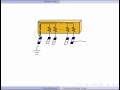
Encoders
Keypads (with resistor arrays)
Active low signals
"No connection" pins
Watch videos and do quiz before
lab!
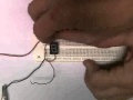
Input device: Keypad
|
|
| Jan. 31 |
This week you'll learn to use a keypad for digital input.
-
Review:
Debugger boards [HTML]
[
May 12, 2017
]
-
Review:
Switches [PDF]
[
April 6, 2011
]
New Device:
Keypads [PDF]
[
October 13, 2011
]
Keypads
[HTML version]
[
May 12, 2017
]
-
New Device:
Resistor Arrays [PDF]
[
April 7, 2011
]
Resistor Arrays
[HTML version]
[
May 12, 2017
]
-
New Device:
Encoders [PDF]
[
January 26, 2012
]
-
Lab:
Encoders
[
September 18, 2017
]
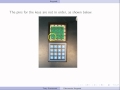
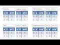
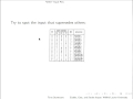
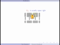
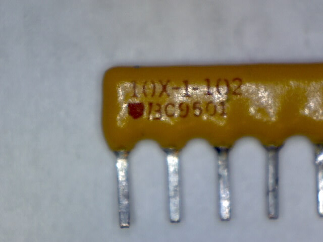
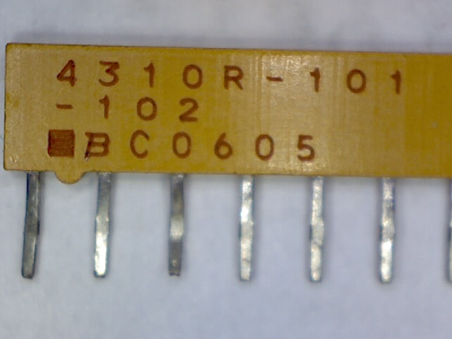
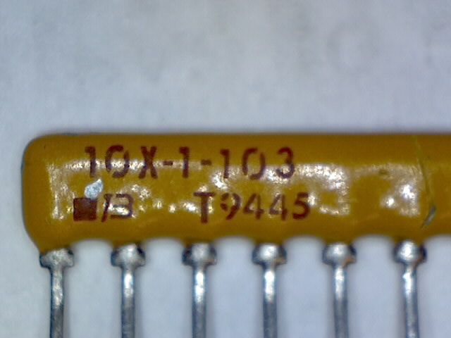
Be sure to put the resistor arrays back in the correct bin
after the lab. To identify the value, look at the number
printed on the array, as in the following examples:
-
1kΩ
Note the 3 digits after the second dash.
The number 102
indicates the resistor value of 10x
102Ω, or 1000 Ω
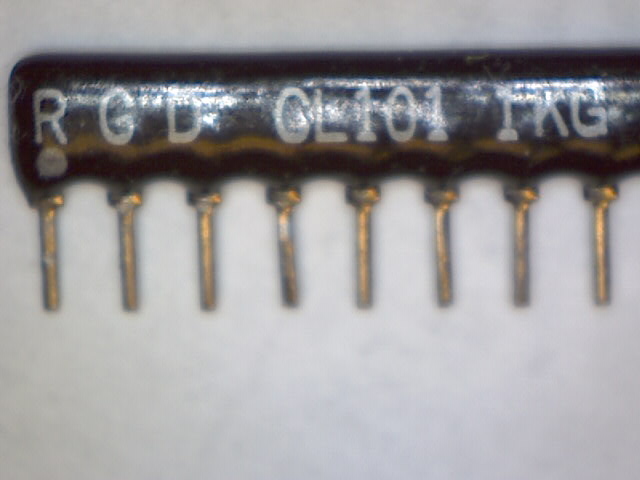
-
1kΩ
Note the 3 digits after the second dash.
-
1kΩ
Note the 1K on the right.
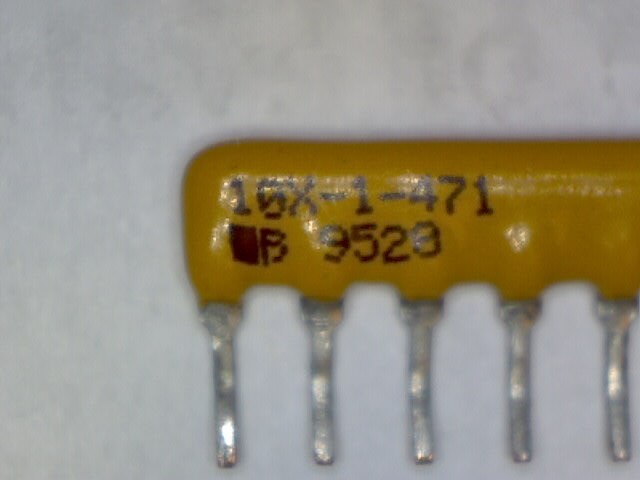
-
470 Ω
Note the 3 digits after the second dash.
The number 471
indicates the resistor value of 47x
101Ω, or 470 Ω
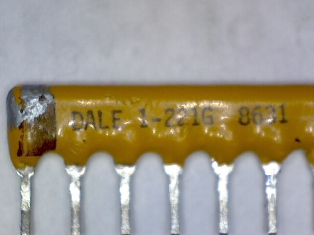
-
220 Ω
Note the 3 digits after the dash.
-
10kΩ
Note the 3 digits after the second dash.
-
There is no quiz this week, but you could
use
the time to work ahead on next week's lab, since it is virtual
and may take a while.
|
Keypads [screencast of PDF]
Resistor Arrays [screencast of PDF]
Encoders [screencast of PDF]

|
|
Priority
encoders
How to cascade encoders
|
|
Computer algebra to test example
Watch videos and do quiz before
lab!
Review of Design skill: Testing logic with a computer
algebra system
|
|
| Feb. 7 |
Drawing a circuit diagram and simulating its operation can be done
with software. This week you'll learn how.
-
prime number identifier
[
April 29, 2015
]
Here's the original project description:
Prime or not?
- -4 inputs, giving binary number
- -1 output, indicating whether the number is prime or
not
-
Lab:Maxima example
-
There is no quiz this week, but you could
use
the time to work ahead on next week's lab, which is
Phase II of the project
and may take a while.
|
|
|
|
|
Project Phase II
Instructions on MyLearningSpace
|
|
| Feb. 14 |
This week you'll learn how to use software to test logic.
-
Prepare project Phase II for
next lab period
Phase II checklist
[
April 29, 2015
]
Sample Phase II
(using Karnaugh maps and Maxima)
prime number identifier
[
April 29, 2015
]
Another Sample Phase II
(using Boolean algebra and Maple)
flag identifier
[
April 29, 2015
]
Sample Revised Phase I
Phase I
(revised)example
[
April 29, 2015
]
NEW Another Sample
Phase II
(using Karnaugh maps and Maxima)
number of segments
[
December 18, 2018
]
-
Before next lab: Read documents (or watch videos) about
7 segment displays
and then do the quiz on MyLearningSpace.
The quiz will be available from Friday at 7 a.m. until
Sunday
at 11:30 p.m. It will not be available
the day of your lab, so you
must do it ahead of time.
|
|
Minimal Boolean Expressions [video]
Karnaugh Maps (K-Maps) [video]

Don't Cares [video]

Karnaugh
Maps
|
|
Reading Week
|
|
| Feb. 21 |
READING WEEK - No labs
|
|
|
|
|
Decoders
Gates with "extra" inputs; strobes, enables, etc.
7 segment displays
Push button (or momentary) switches
Watch videos and do quiz before
lab!
Input device: Pushbutton switch
Output device: 7 Segment display
|
|
| Feb. 28 |
This week you'll learn to use momentary switches for digital input,
and 7 segment displays for output.
-
Review:
Light Emitting Diodes (LEDs) [PDF]
[
April 17, 2012
]
Light Emmitting Diodes (LEDs)
[HTML version]
[
May 12, 2017
]
New Device:
7 Segment Displays [PDF]
[
April 6, 2011
]
7 Segment Displays
[HTML version]
[
May 12, 2017
]
-
Review:
Switches [PDF]
[
April 6, 2011
]
New Device:
Pushbutton Switches [PDF]
[
October 21, 2011
]
Pushbutton
Switches
[HTML version]
[
October 11, 2019
]
Alternative Device:
Momentary Switches [PDF]
[
October 22, 2015
]
-
Review:
Enable, Gate, and Strobe Inputs [PDF]
[
January 31, 2014
]
-
New Device:
Decoders [PDF]
[
January 27, 2012
]
-
Lab:
Decoders
[
October 11, 2019
]
-
There is no quiz this week, but you could
use
the time to work ahead on next week's lab, since it is virtual
and may take a while.
|
Pushbutton Switches [screencast of PDF]

7 Segment Displays [screencast of PDF]

Testing a Common Cathode 7 Segment Display [video]

Testing a Common Anode 7 Segment Display [video]
Decoders [screencast of PDF]

Enable, Gate and Strobe inputs [screencast of PDF]
|
Minimal Boolean Expressions [video]
Karnaugh Maps (K-Maps) [video]
Don't Cares [video]
Display
decoders
Karnaugh
Maps
|
|
Circuitverse to draw and simulate example
Review of Design skill: Circuit drawing and simulation
Design skill: Good drawing for schematics
|
|
| March 7 |
As circuits get larger, how you draw them makes a big
difference in how easy they are to debug. This week you'll learn
how.
-
New Information:
Drawing tips for digital circuits [PDF]
[
November 14, 2018
]
Drawing tips for digital circuits
[HTML version]
[
November 14, 2018
]
-
prime number identifier
[
April 29, 2015
]
Here's the original project description:
Prime or not?
- -4 inputs, giving binary number
- -1 output, indicating whether the number is prime or
not
-
Lab: Circuitverse example
-
Before next lab: Read the document
(or watch videos) about
enable, gate, and strobe inputs
and then do the quiz on MyLearningSpace.
The quiz will be available from Friday at 7 a.m. until
Sunday
at 11:30 p.m. It will not be available
the day of your lab, so you
must do it ahead of time.
|
Drawing tips for digital circuits [screencast of PDF]

|
|
|
|
Design Project: Tinkercad Introduction
|
|
| March 14 |
-
Lab on MyLearningSpace
After using real breadboards, switches, LEDs, etc. this should
be easy to understand. It will be needed for the final project
submission.
|
|
|
|
|
Design Project
|
|
| March 21 |
|
|
|
|
|
Design Project: Final submission
|
|
| March 28 |
|
|
|
|


