Pages created and updated by
Terry Sturtevant
Date Posted:
October 11, 2019
A pushbutton switch is like any other switch; it needs to be
used
with a resistor
to provide input to a logic gate. They are momentary; i.e. they
are only connected as long as the button is held down.
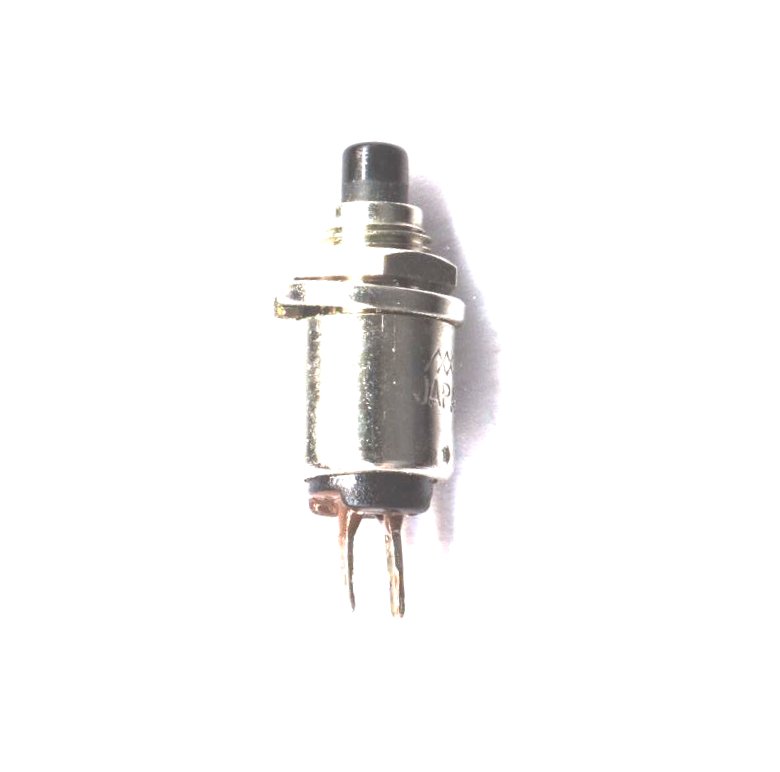
These switches are handy because the pins will fit in a breadboard.

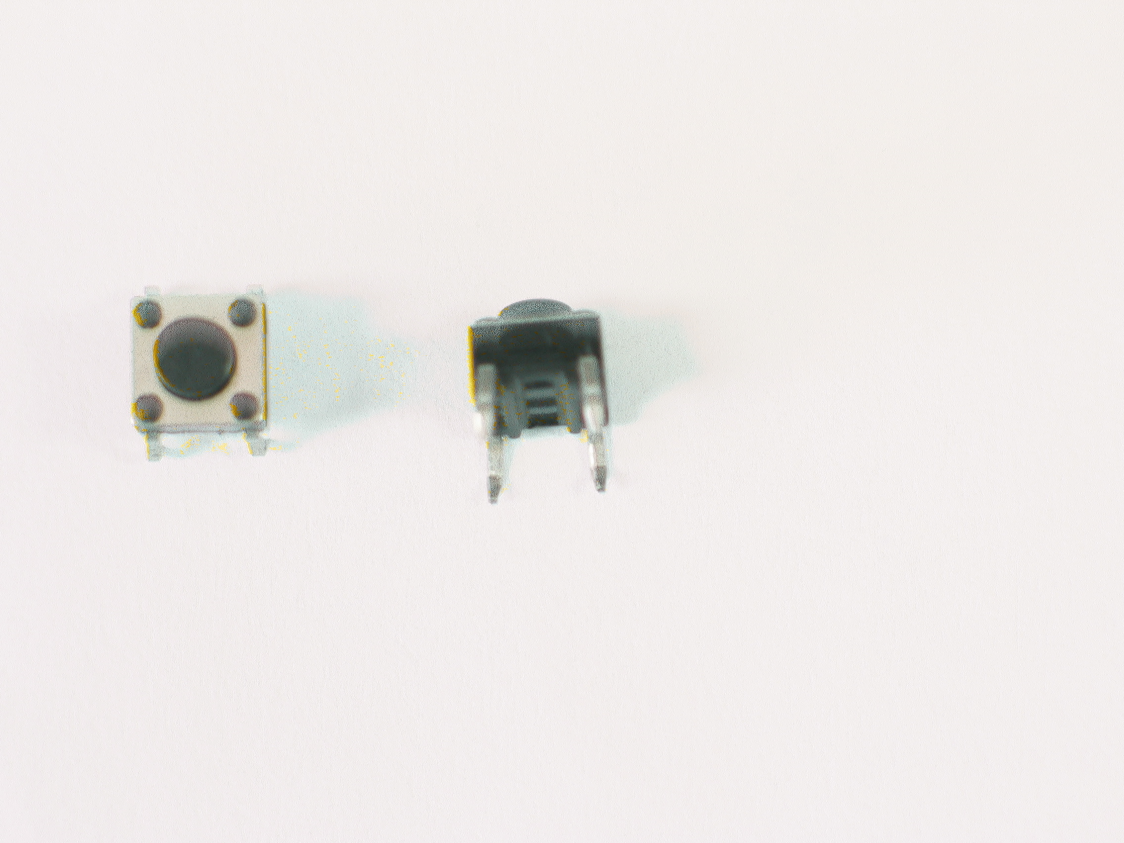
An alternative version looks like this:
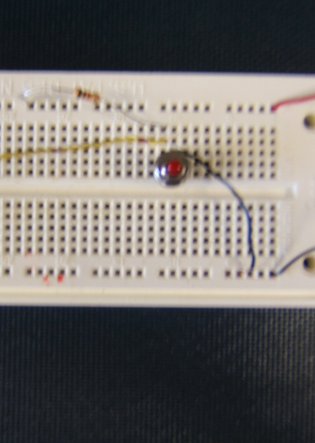
You can use a switch with either a "pull-up" resistor or a "pull-down" resistor,
depending on whether you want the signal to be high or low when the button
is unpressed.
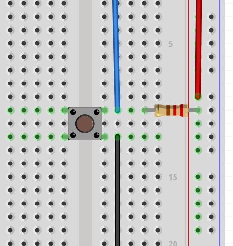
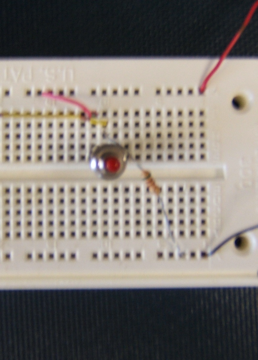
Here is a switch with a pull-up resistor. (The signal is the yellow
wire.):
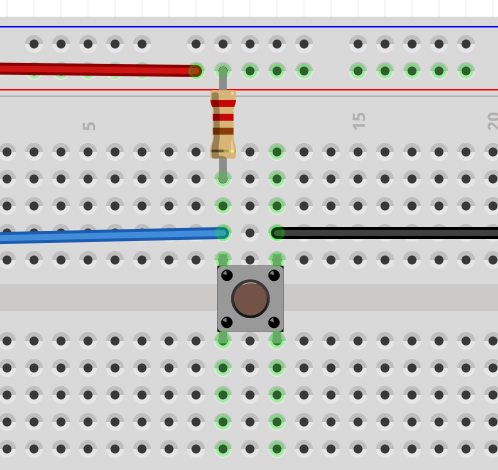
Here's the alternative type (The signal is the blue wire.):
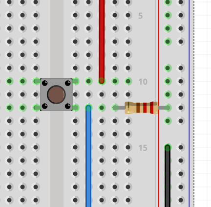
Here is a switch with a pull-down resistor. (The signal is the yellow
wire.):
Here's the alternative type (The signal is the blue wire.):
Note that in each case, the output comes from the place where the
resistor and switch connect. ( In other words, from the same row of
the breadboard as the resistor.)
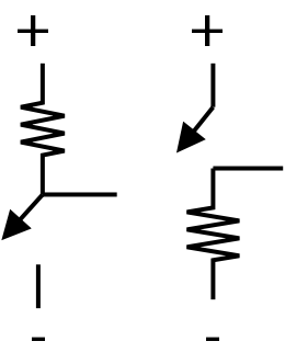
Here's a schematic of the connections, which may make it easier to visualize:
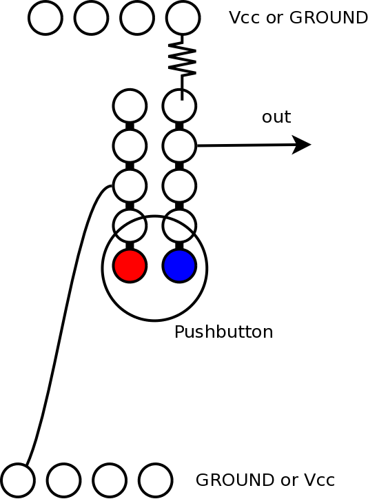
Rotating the figure for the other type makes it easy to see the
same setup. The blue wire is the signal. (It's reversed, left to
right.):


![]()
Wilfrid Laurier University
© 2019 Wilfrid Laurier University