PC/CP220 Digital Electronics Lab
Decoder Lab
Objective:
- Understand the functionality of the 7-segment display
- Understand the 74LS48
BCD-to-7-segment decoder
- Wire a BCD-to-7-segment decoder circuit
- Use a momentary (pushbutton) switch
Background:
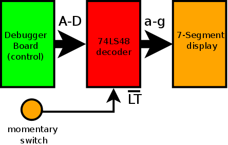
In this lab you will wire a
BCD-to-7-segment decoder
with a 7 segment display
and a
pushbutton (or momentary) switch
.
Display unit
You will be using a 7-segment
display.
Decoder
This chip has 4 inputs, probably labeled A to D,
and 7 outputs, probably labeled a to g,
to light up the appropriate segments of the display.
There may be additional inputs and outputs for additional functionality.
You should choose a decoder chip that corresponds to your display; i.e.
if you're using a common-anode display, then use a common-anode decoder.
If you're using a common-cathode display, then use a common-cathode
decoder. Otherwise you'll need to have inverters on each of the lines
between the decoder and the display.
Dealing with enables, gates, strobes, etc.
Many chips which have logic in them also have pins which
control overall function of the device, such as whether the
outputs should function or not. These pins are usually called
enables,
gates,
or
strobes.
To determine whether such pins exist, look at the truth table.
See if there are any places where the outputs are not
what you expect. See which inputs control this.
After having found any of these pins, usually you would tie them to
power or ground so
that the chip functions as expected.
In this lab, you will use a
pushbutton switch
to control
one of them to show the effect.
Task:
Parts list
- One breadboard
- One decoder 74LS48
- One 7- segment Display
- Debugger board
- Pushbutton (momentary) switch
- Resistors as needed
Switches and LEDs typically use different resistor values;
1kΩ is good for switches, while something smaller such as
470Ω is better for LEDs.
Wiring a Decoder with I/O
In this lab you will wire a
BCD-to-7-segment decoder
with a 7 segment display.
The
schematic diagram will not be given; you will need to
figure out
your circuit layout and how to
connect the circuit components.
-
Examine the
pinout
of the
NES-5011,
(alternate link),
7-segment display used in the
lab before you start wiring.
Since this device doesn't have a notch at one end to indicate pin 1,
look at the data sheet to figure out which pin is pin 1.
Then figure out which pin corresponds to which
input.
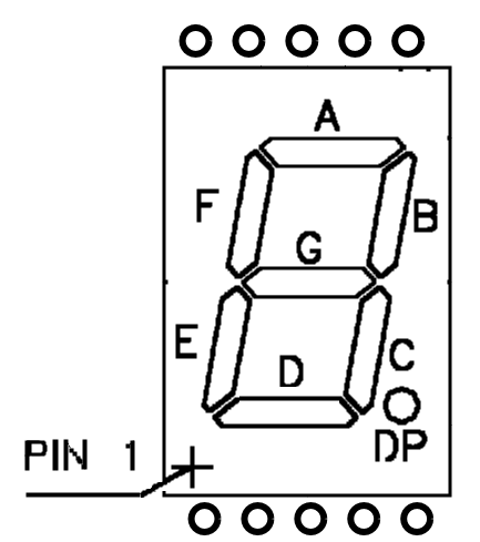
Write the pin designations on the pinout sheet that looks like this image to help you with
your wiring.
Your display has a
common cathode
that requires the driver (decoder) to provide
a high-level voltage to activate a segment.
The common pin is connected internally and
only needs to be grounded from one side.
Does the datasheet actually use the phrase "common-cathode" anywhere? If
not,
how can you figure out which type it is?
(Hint: Look at the diagrams of the circuitry inside the chip, and then
look back at the earlier handout about LEDs.)
Since each segment of the display is an LED, you'll need to use
resistors
just as you would for discrete LEDs.
Since all of the LED segments are connected to the common pin, you could
use a single resistor between the common pin and power or ground,
(depending on whether the display is common anode or common cathode),
to limit the current to all of the LEDs. The only drawback with this is
that you might notice the display is dimmer when more segments are on.
(Hint: If you choose to use individual resistors, you can
use the resistors to connect the
decoder to the display, instead of having wires to connect the
decoder to the resistors and wires to connect
the resistors to the display
then you will
save a lot of wiring.)
-
Put the 7 segment display and resistor(s) at one end of the breadboard.
This is the output module.
-
Use
a wire to power or ground as needed
to test each of the 7 display segments . (As long as the resistor(s) for
the 7 segment display are in place, this should be fine.)
(You don't have to test the decimal point(s).)
-
Put the pushbutton switch (with its resistor)
at the other end of the breadboard. Wire it for active LOW
operation.
This, along with the debugger board, is the input module.
Be sure to
daisy-chain
the breadboard and the debugger board,
rather than using several clip leads or having clip leads holding more
than one wire.
-
Using the debugger board, test to see that when the pushbutton is
pressed, the output is LOW, and when it is unpressed, the output is
HIGH.
- Examine the datasheet for the
74LS48 seven segment display decoder
.
Notice that the 74LS48 has 3 "extra" pins;
LT,
BI, and
BI/RBO.
Look at the device truth
table to figure out which of these pins are inputs, and whether
the ones which are inputs need to be tied
high or low.
Is this decoder designed for common cathode or common anode displays?
Does the datasheet actually use the phrase "common-cathode" anywhere? If
not, how can you figure it out?
(Hint: Look at the truth table for a number, such as "zero" and see
whether the appropriate segments are "high" or "low".) Is this correct
for the display you have, or will you need to invert all of the inputs?
-
Put the 74LS48 in the middle of the breadboard, and
use the debugger board for
the
BCD
inputs to the decoder.
Use the pushbutton switch
for
LT.
Tie the other "extra" inputs high or low, as appropriate.
- Connect the input, logic, and output modules and verify that
the 7-segment display show the correct output for
decimal numbers from 0 to 9.
See what happens when you press the pushbutton. Do you understand the
purpose (and the name) of the
LT
input?
Demonstrate the circuit to the lab
demonstrator before you leave.


