Pages created and updated by
Terry Sturtevant
Date Posted:
May 12, 2017
A
keypad
provides an easy input device to a digital circuit. It consists
of several switches,
one under each key, which have one of their two poles in common.
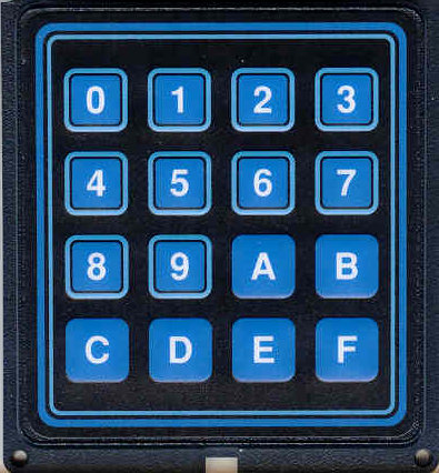
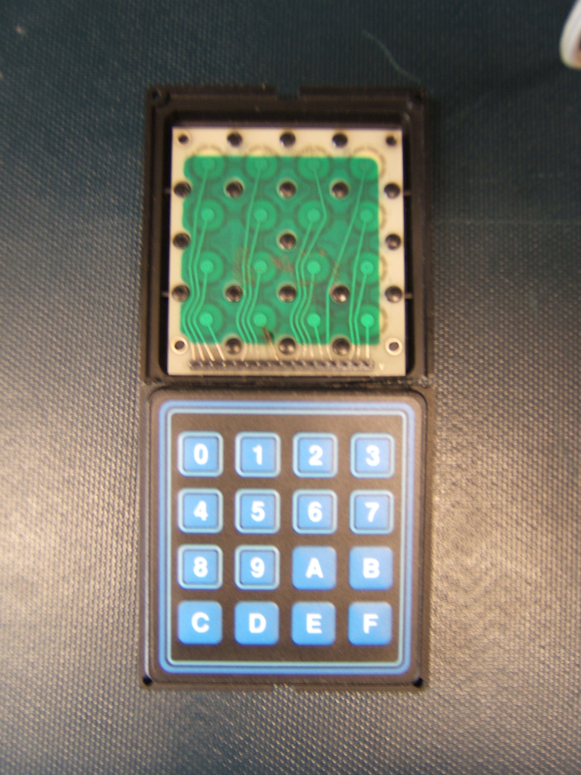
Here are two similar keypads:
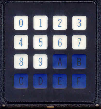
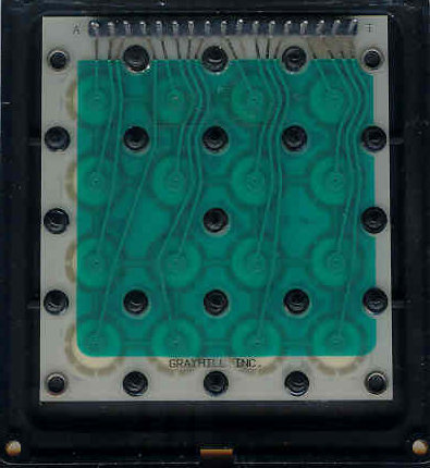
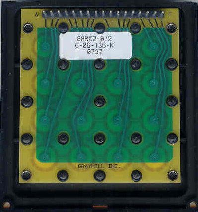
Note that on the back, you can see one pin that does not have a trace going from it. This is the common pin.
The pins for the keypad aren't connected in numerical order.
You can see which pin goes with
which key by looking at the bottom of the keypad.
(If you look for the pin with no visible connection
to a key, you can find the common pin.)
Because the side-by-side image is reversed left-to-right when it's upside down,
it may be easier to figure out in the following diagram:
Here's how the pin connections go, looking from the top:
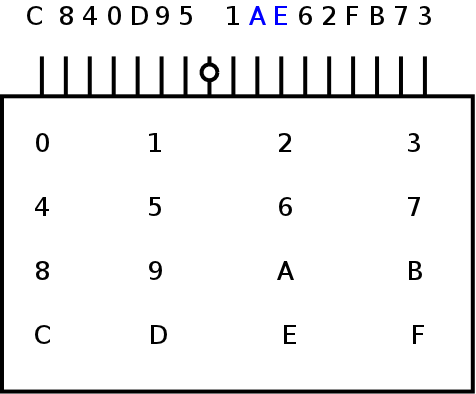
The common pin has the circle drawn on it.
(Note that A and E don't follow the normal pattern.)
To use a key to send a HIGH (1) signal,
one must connect the common pin to 5 volt supply and put a resistor
to ground from each of the other pins,
as with the DIP switch package. Using 16 individual resistors to
do this it would be rather tedious,
so we will once again use the resistor arrays.
The particular resistor array which we will use has
several resistors in it which all have one end in common.
Since the common pin for the keypad is sort of
in the middle,
note that the resistor array on the left has to have its common pin on
the left, while the resistor array on the right has to have its common
pin on the right.
In some cases you will be using the keypad for input to devices which use active low inputs. This means that you will want a key pressed to give a low output on the corresponding line. To do this, simply switch the common connections of the keypad and resistor array mentioned above. This means you will connect the common pin of the keypad to ground and the resistor array to Vcc (+5V).
The actual resistor value isn't critical; anything between about 100 Ω and 1 k Ω should work. If the resistors get too large, then the circuit will stop working; if the resistors get too small, there will be excessive current drawn from the circuit. Ideally you want to choose a large value that works consistently.


![]()
Wilfrid Laurier University
© 2019 Wilfrid Laurier University