Introduction to Breadboards
Here is a view of a simple breadboard.
[click image to get a larger image]
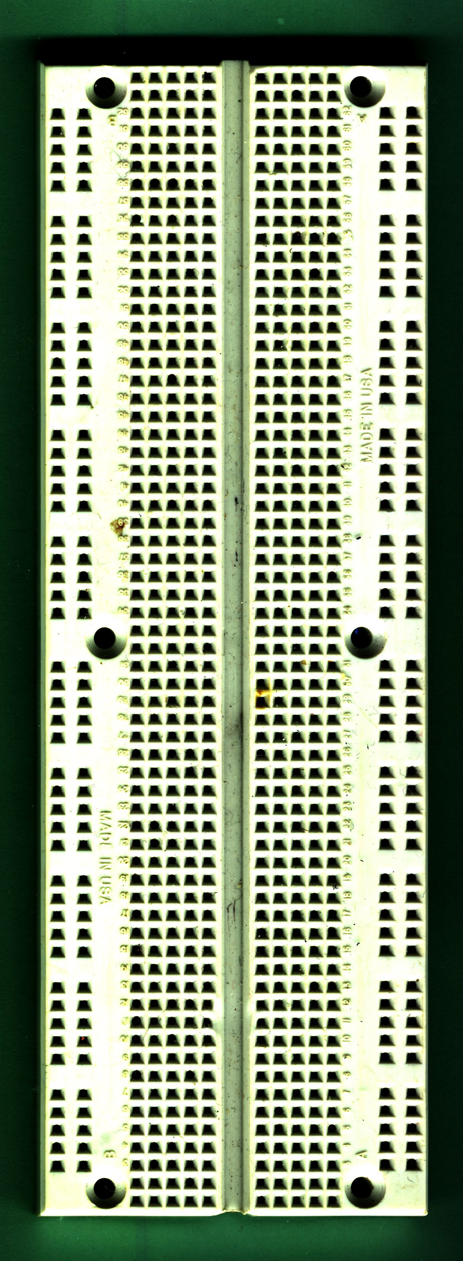
Here's a view of the back with the paper cover removed.
[click image to get a larger image]
You can see how the holes on the top are connected underneath;
each row of 5 across on one side of the trough is connected,
but the rows down each side are connected all the way.
These side rows cab be called
"busses".
Here's another breadboard, with more busses. Notice there are two rows
on each side.
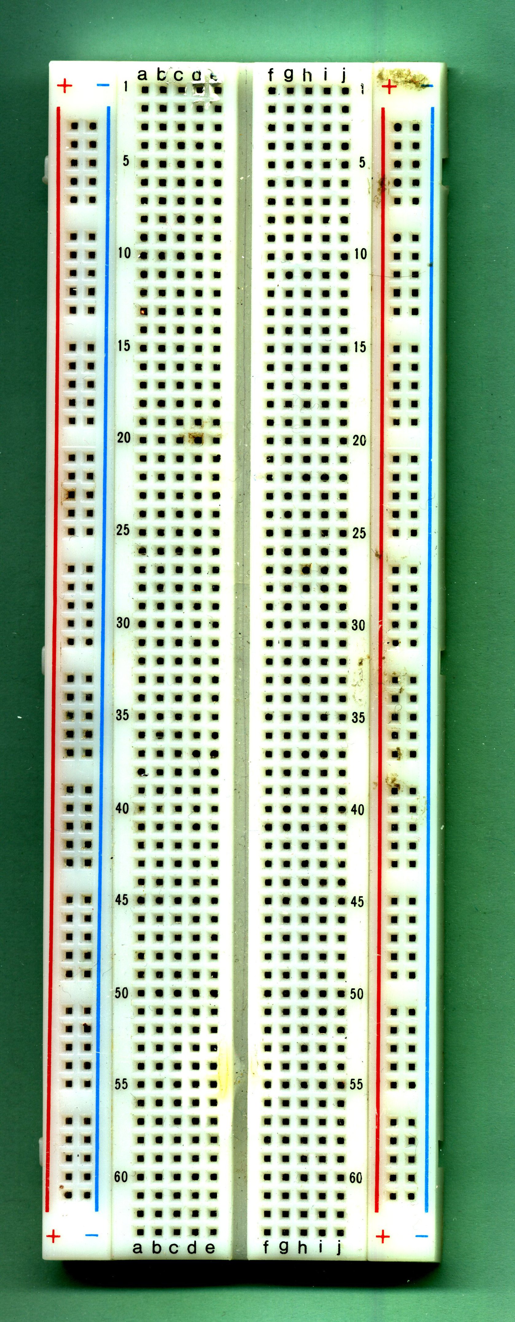
[click image to get a larger image]
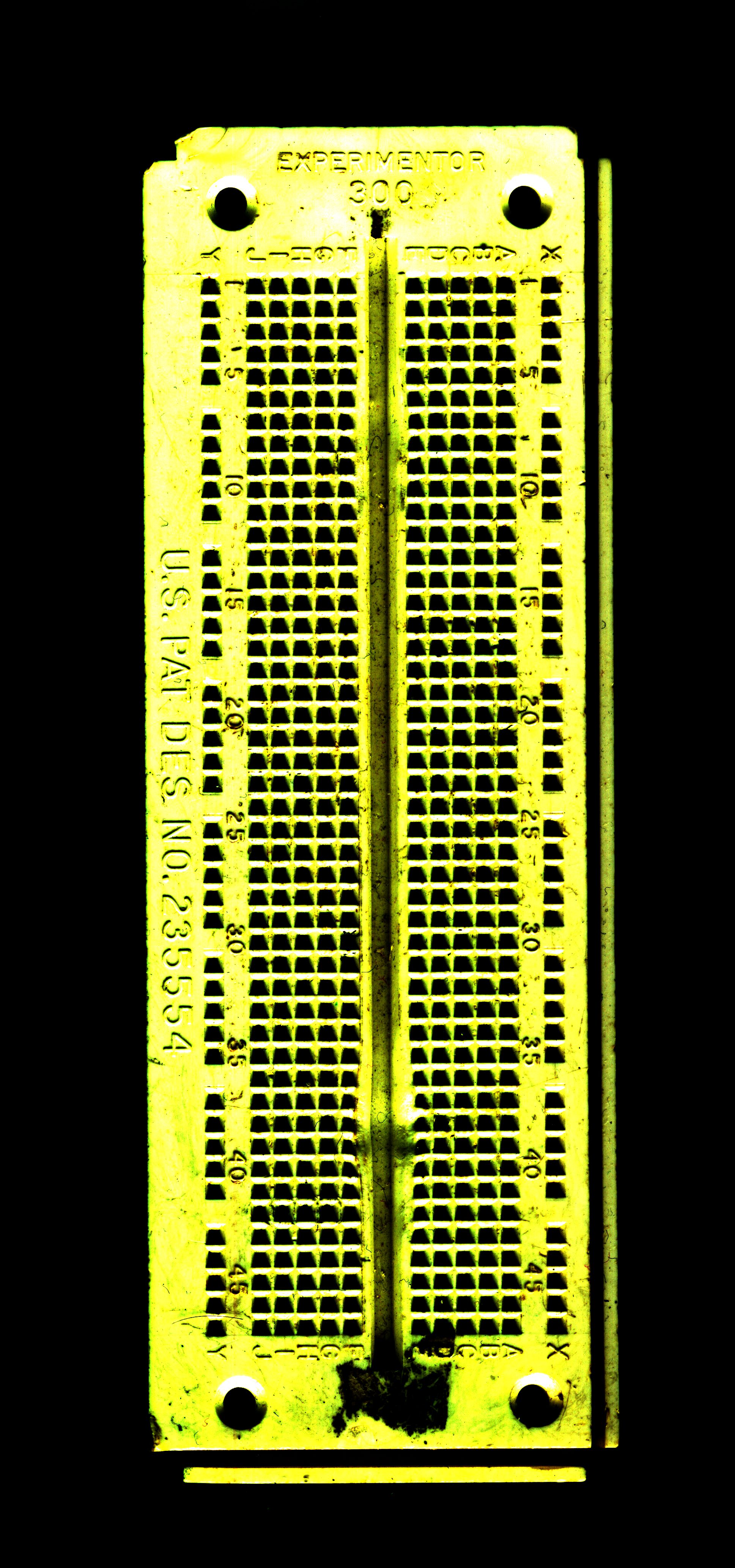
Here's another.
[click image to get a larger image]
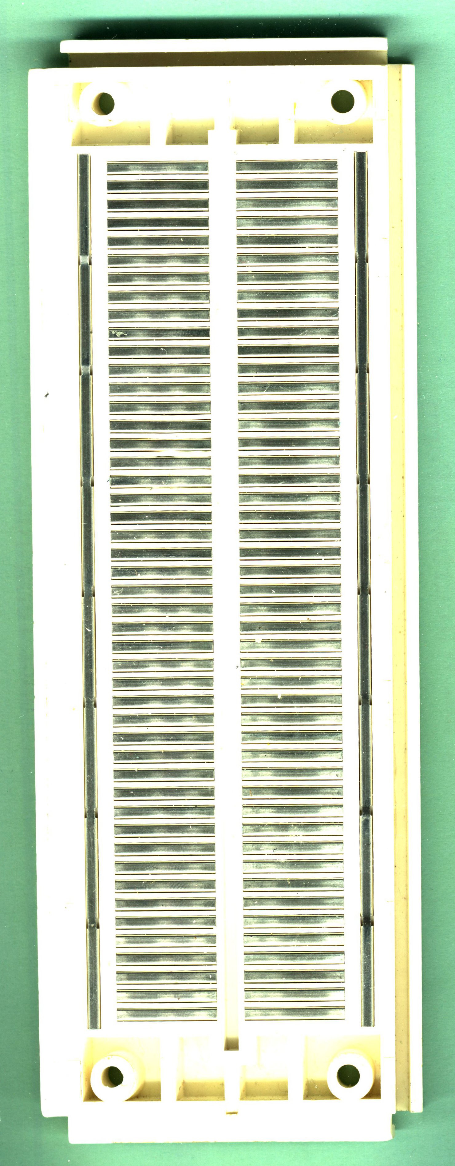
And here's the back with the paper cover removed.
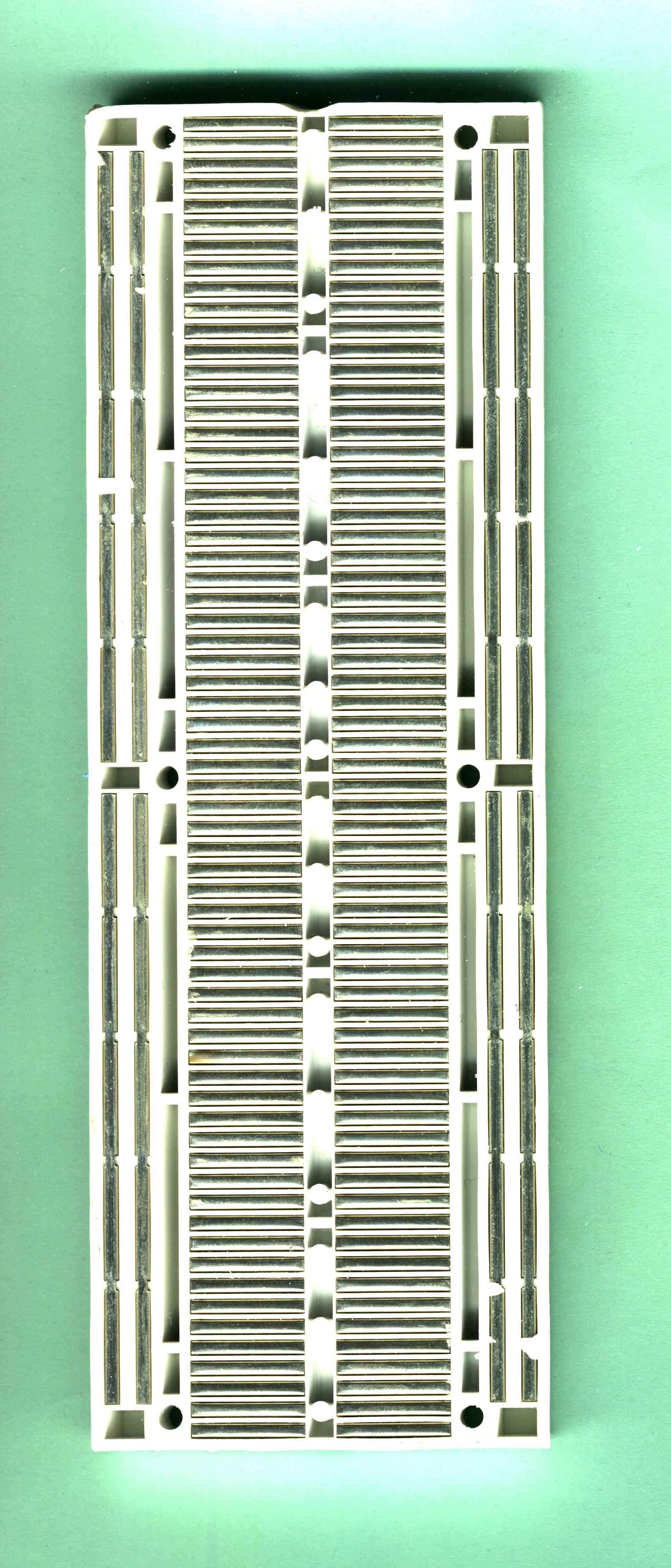
[click image to get a larger image]
Notice one big change from the first breadboard; the side busses are
each only connected
halfway down the board. They stop at the
middle, so that the top and bottom aren't connected to each other.
This means that, if you want, you can actually think of this board as
having
eight busses, rather than four.
Wiring with Breadboards
Here is one chip on a breadboard:
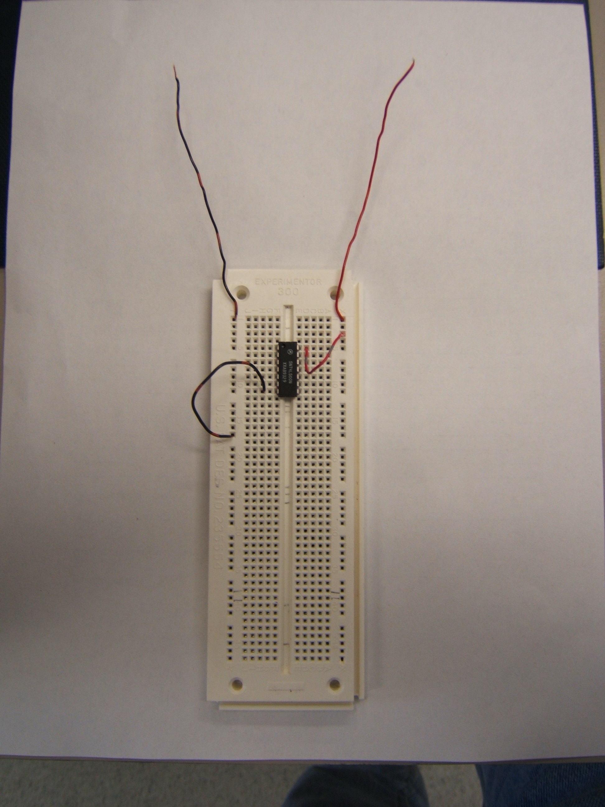
[click image to get a larger image]
For many chips, the GROUND pin is on the lower left and POWER is on the
upper right, so using the left bus for ground and the right for power
makes a lot of sense.
Here are two chips on a breadboard. Note how the use of the "busses"
along the side make wiring easier, especially when using multiple chips.
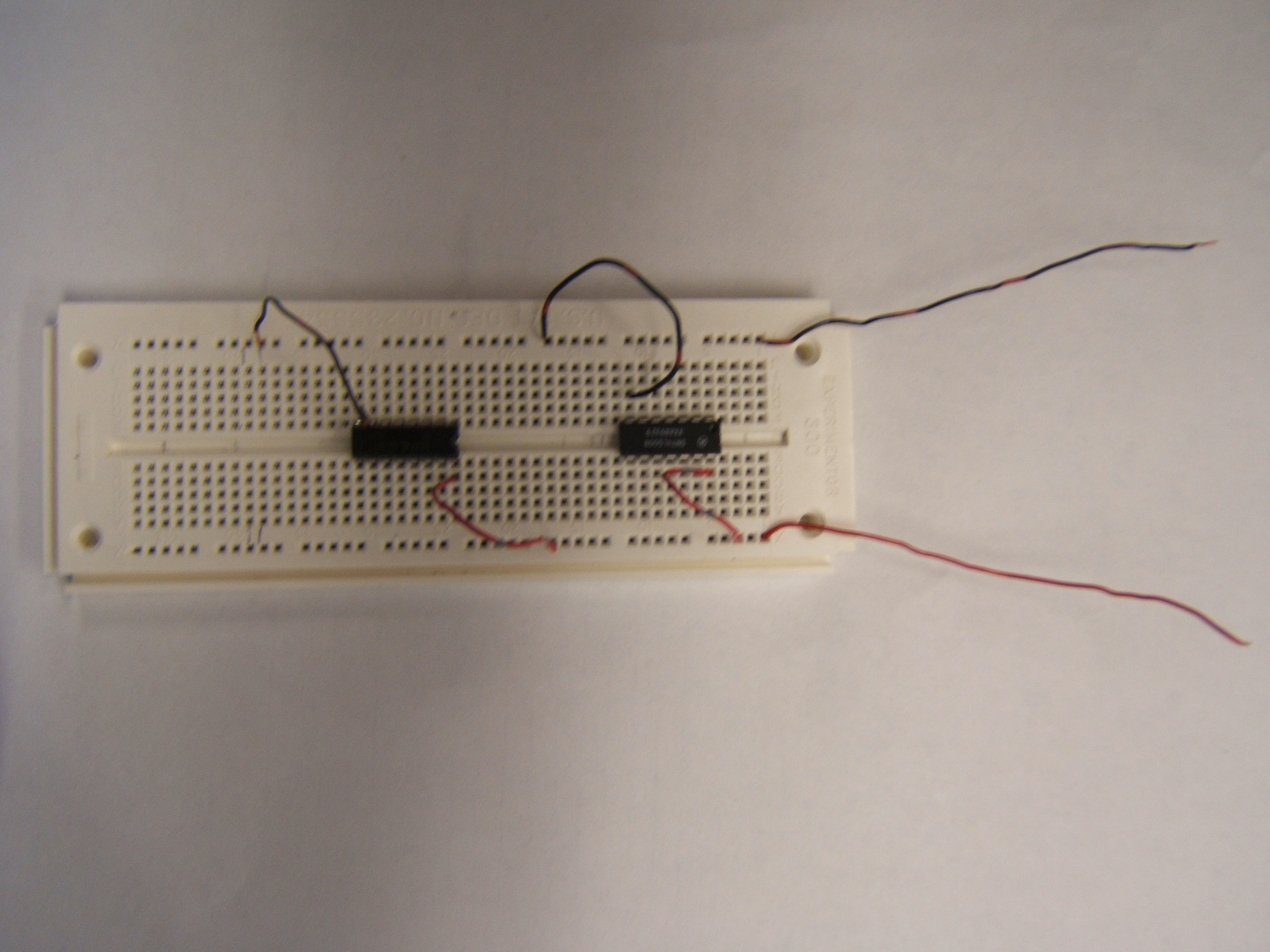
[click image to get a larger image]
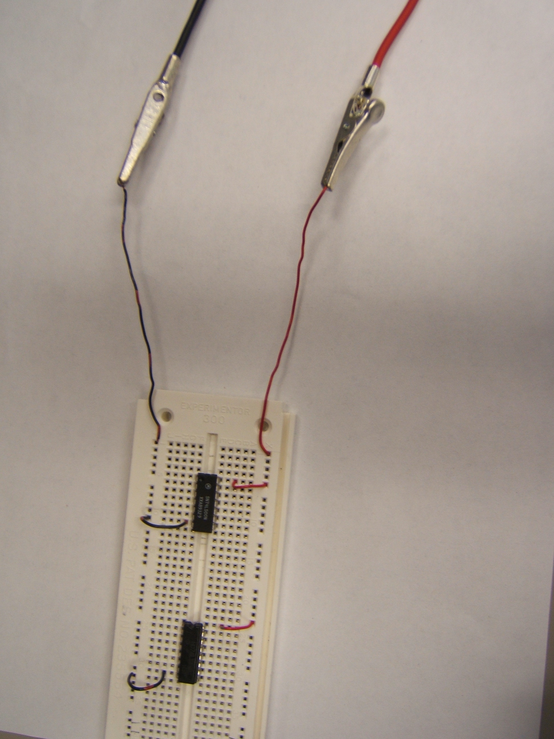
By cutting wires to a reasonable length, the circuit can be made
tidier and easier to debug. (This figure also shows how clip leads are
attached; they're connected to the busses,
not to individual
chips.)
[click image to get a larger image]
Connecting the board to the bench supply can be done like this
(Note how I have consistently used only red wires for power and black
wires for ground.):
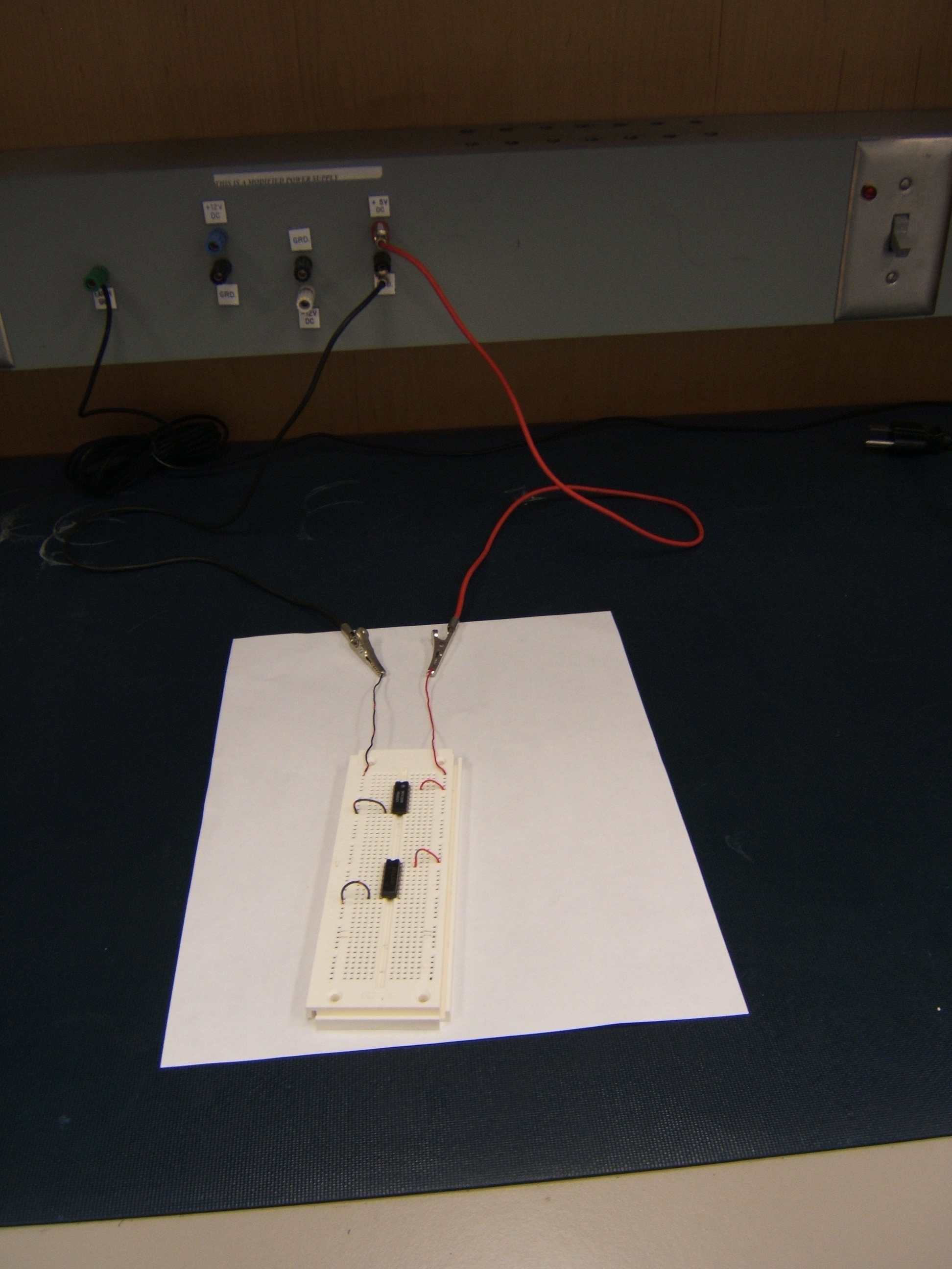
[click image to get a larger image]
Here's a close-up of one way to connect the alligator clips to the
bench supply:
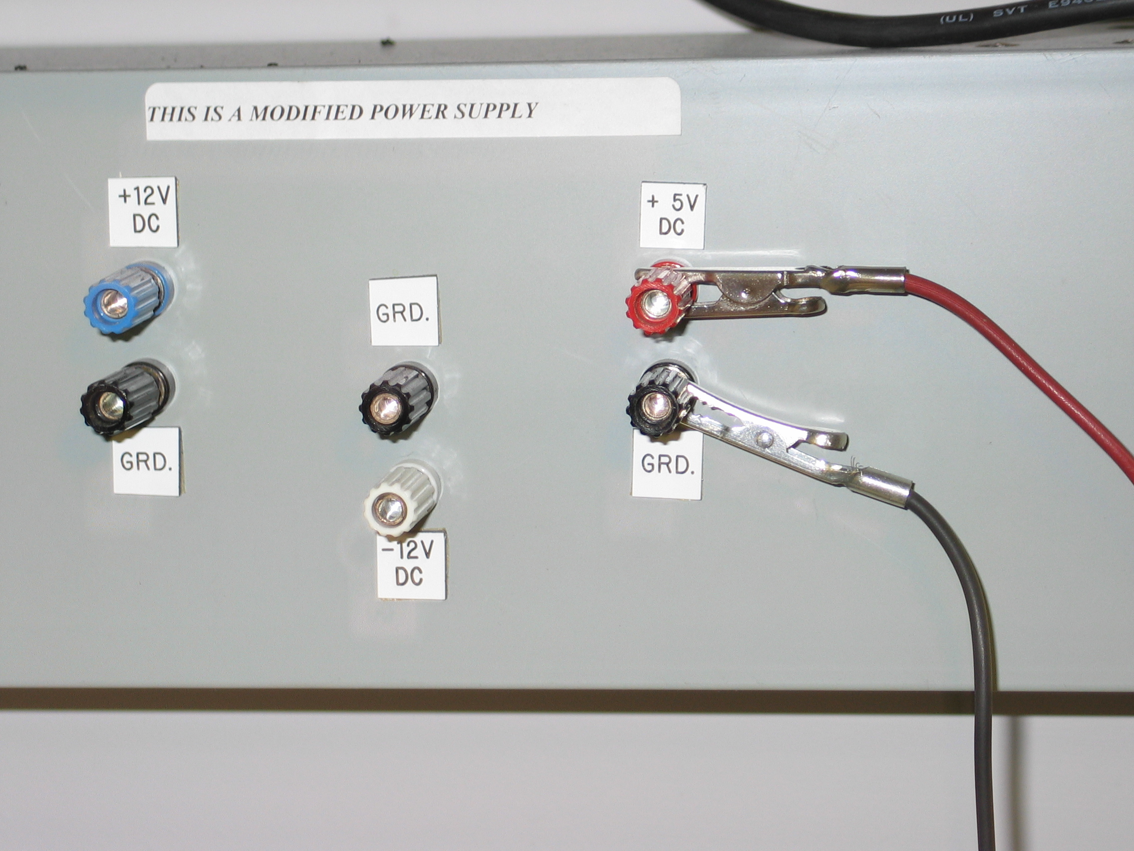
[click image to get a larger image]
This way is better; note the clips are very firmly attached and
can't short out to one another.
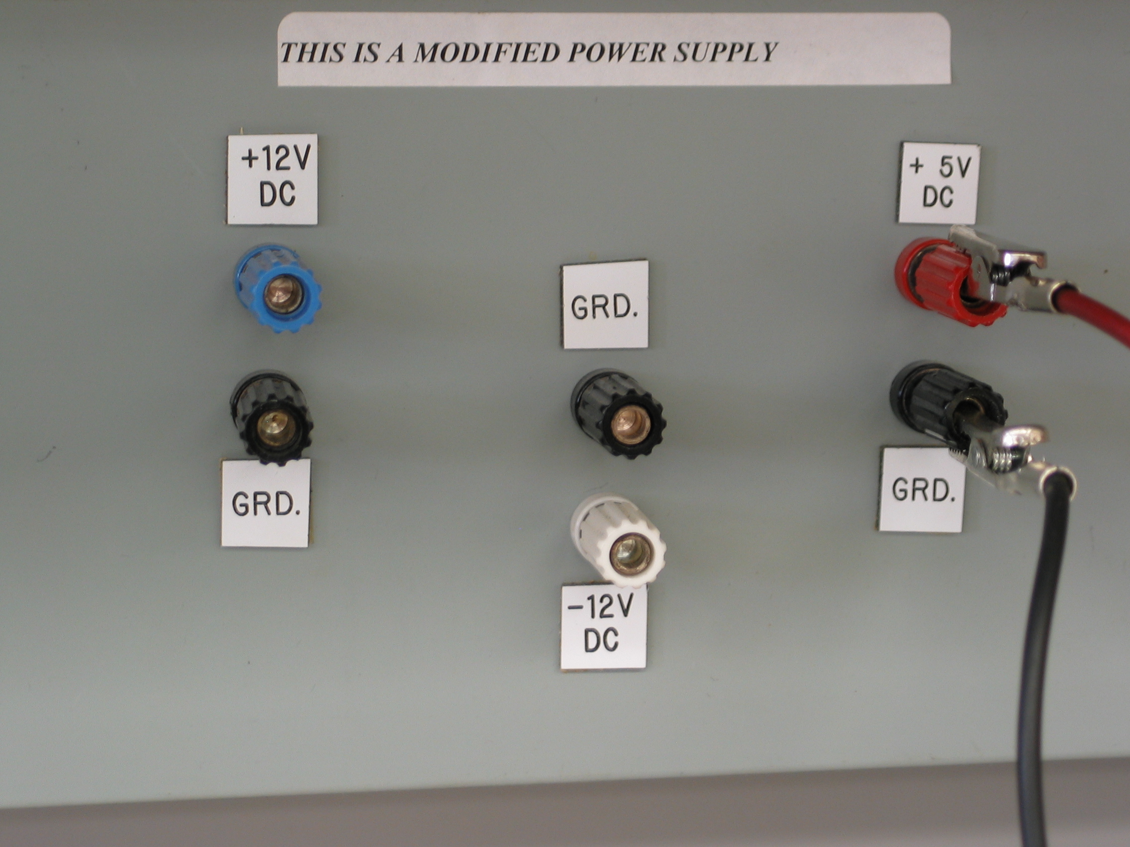
[click image to get a larger image]
Here's how to combine multiple boards,
including debugger boards.
Note that doing it this way means that each clip lead
only
clips to a single wire.
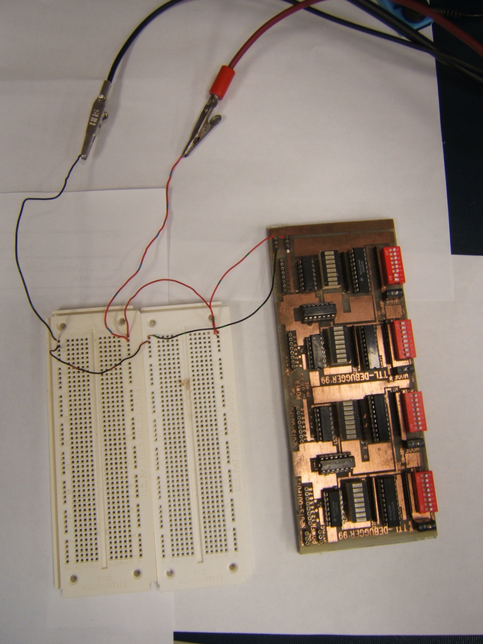
[click image to get a larger image]


