Pages created and updated by
Terry Sturtevant
Date Posted:
May 12, 2017
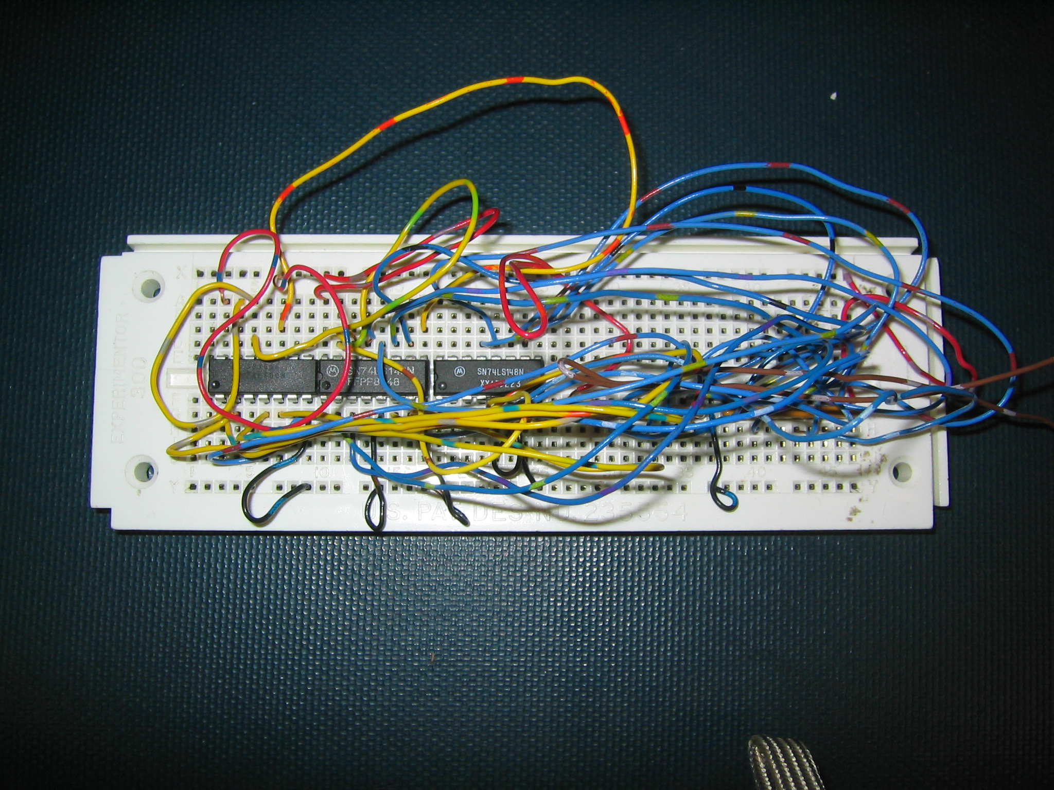
You will use the debugger board (see below) to test whether your circuit is working or not.
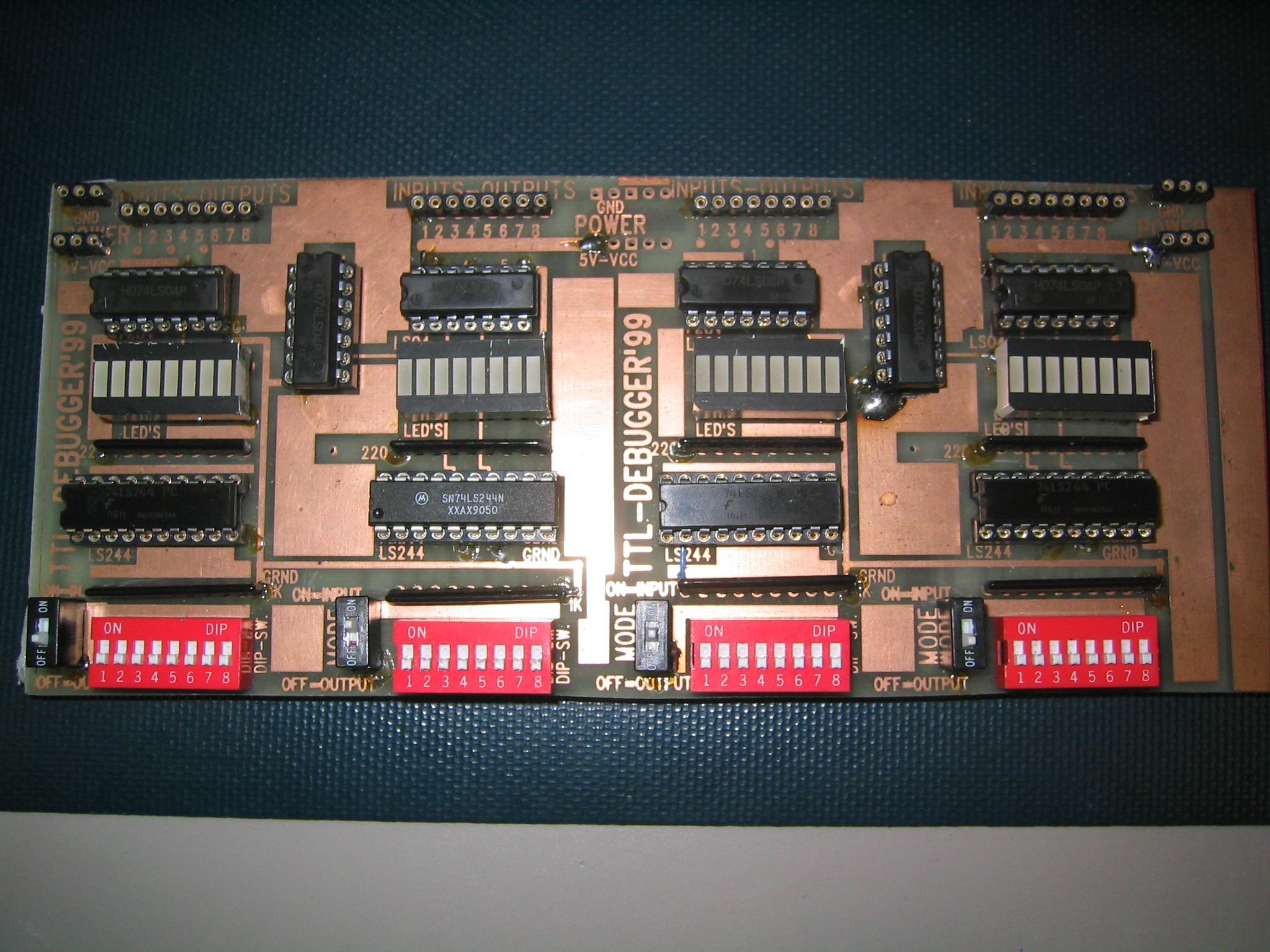
[click image to get a larger image]
Another version looks like this:
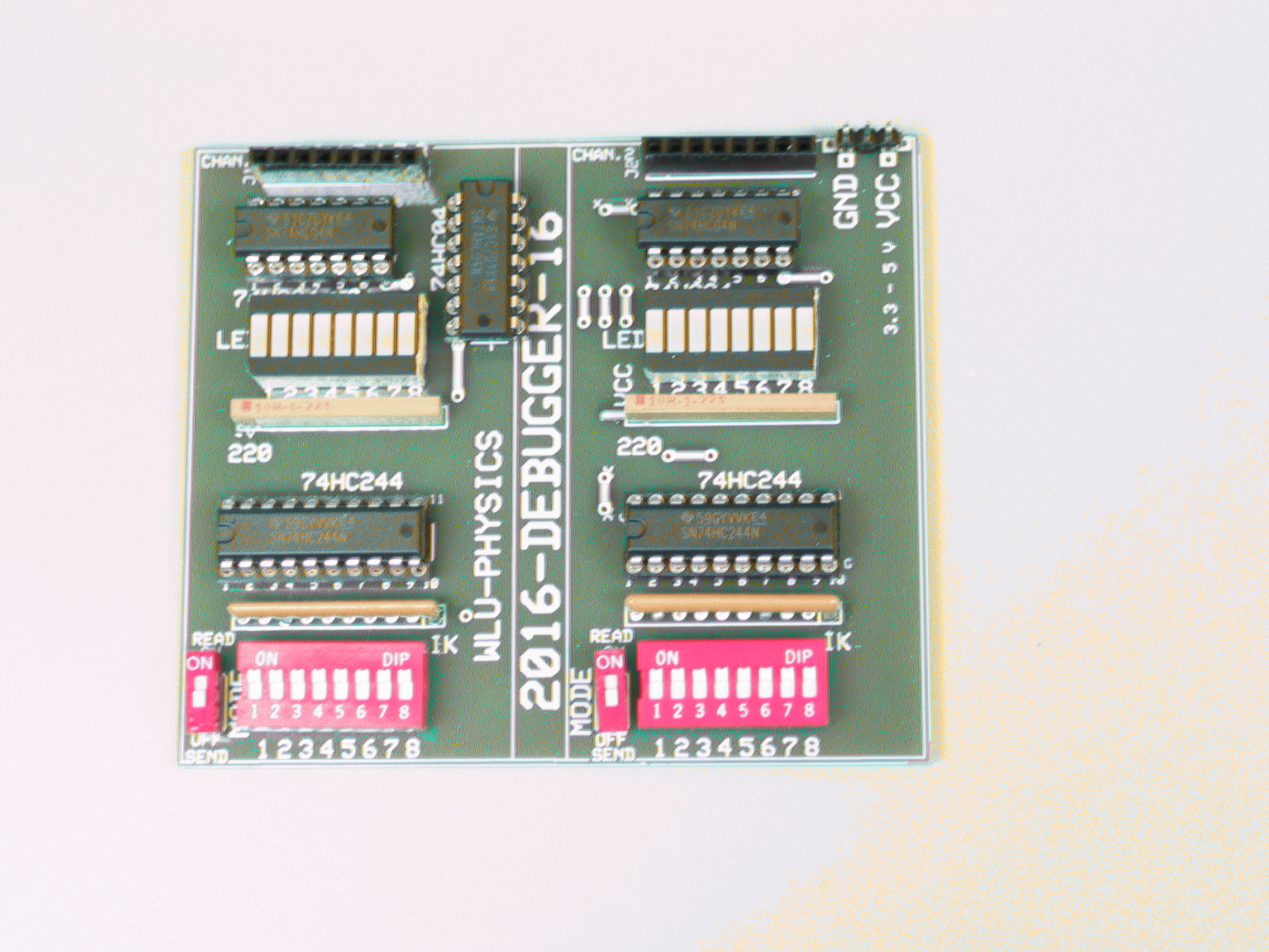
[click image to get a larger image]
The debugger board is set up with either two or four banks
of
eight
signals.
Here's a closer look at a single bank:
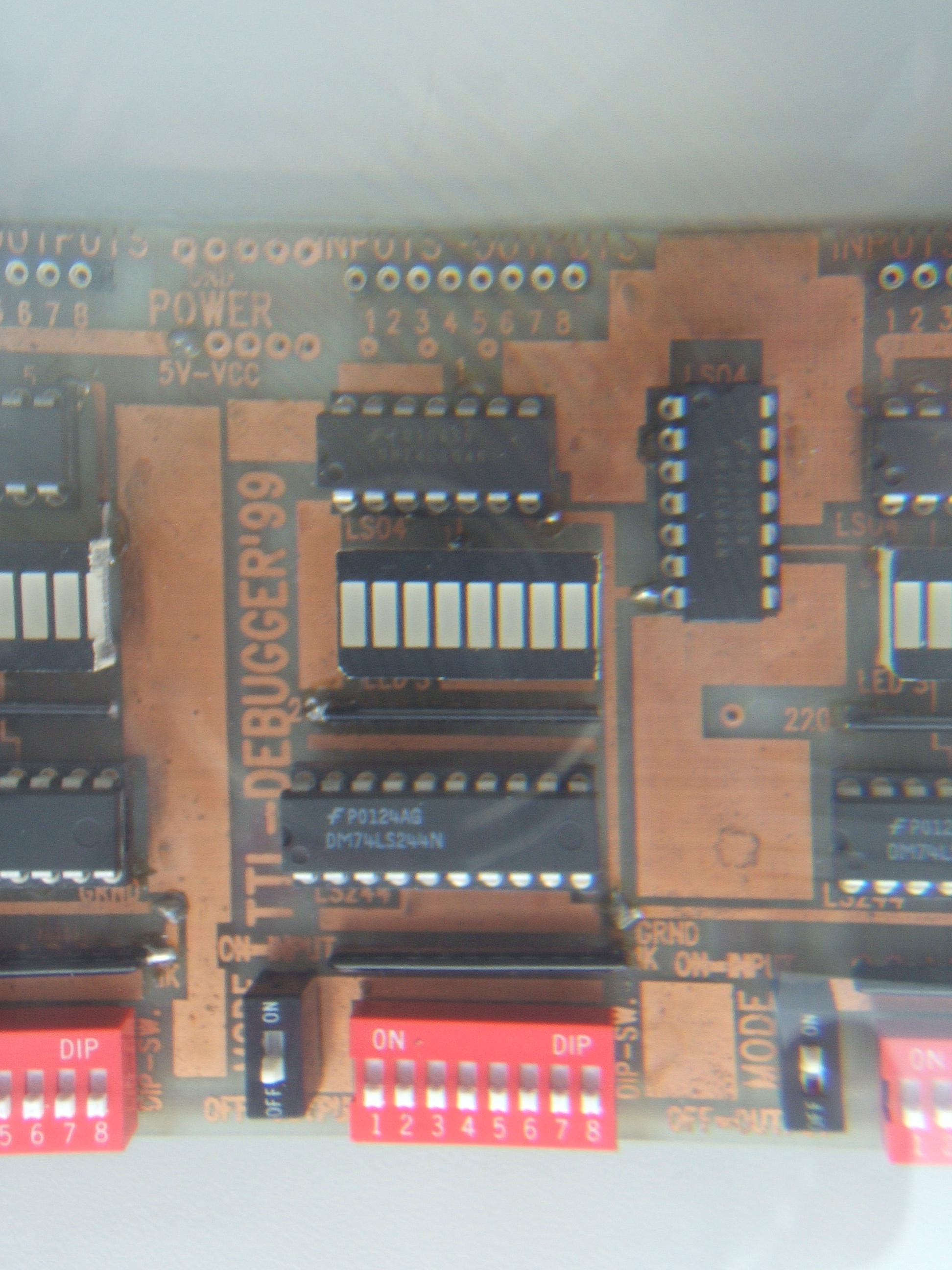
[click image to get a larger image]
Each bank can be configured to either
"display" logic levels in
your circuit or to "control" logic levels
in your circuit. In "display"
mode, you can connect a signal to its corresponding connection on the
debugger board and the LED will be ON if the signal is HIGH and OFF
if it is
LOW.
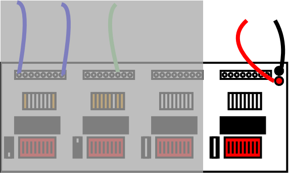
Here's what the debugger board looks like connected:
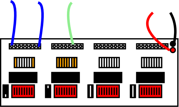
These are the power connections:
This is a bank in "control" mode (i.e. you can use it for
inputs to a circuit):
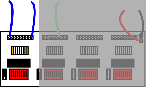
Hint: If you're not using all of the pins in one bank, spread
them out so it's easier to tell which is which.
This is a bank in "display" mode (i.e. you can use it to see the
outputs from a circuit):
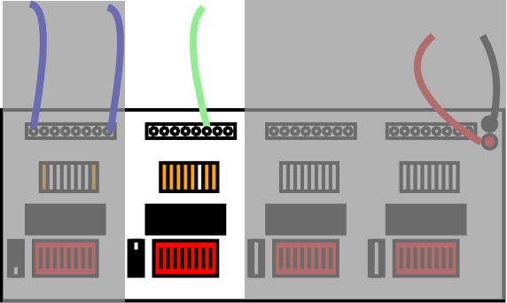
Note: The debugger board has TTL gates on its input. These gates, like most TTL gates, tend to float HIGH if unconnected. Thus, if you have nothing connected to a pin in a bank set for "display" mode, the LED will usually be ON. No connection does not mean LOW; pins must be tied LOW if you want to ensure that they are LOW.
In "control" mode, the DIP switches for a bank of connectors will control the logic level on the pins.
Note: Make sure that you do not try and have two different things trying to control the same signal. For instance, only use the debugger board in "control" mode to connect to inputs of your circuit which are not connected to anything else.
Switching a bank from one mode to the other is accomplished either by a single DIP switch or by a jumper. (You can tell which mode you're in by whether the bank of DIP switches change the LEDS. If so, you're in "control" mode. If not, you're in "display" mode.) The circuits on the debugger board need power and ground to work, so make sure they are connected.
Here are a few important rules to follow when handling ICs during debuging:
Your circuit will probably not work the very first time.
Therefore, trouble-shooting is a basic skill that you will have to learn.
The followings are a list of helpful suggestions:
 .
. 


![]()
Wilfrid Laurier University
© 2019 Wilfrid Laurier University