Pages created and updated by
Terry Sturtevant
Date Posted:
May 12, 2017
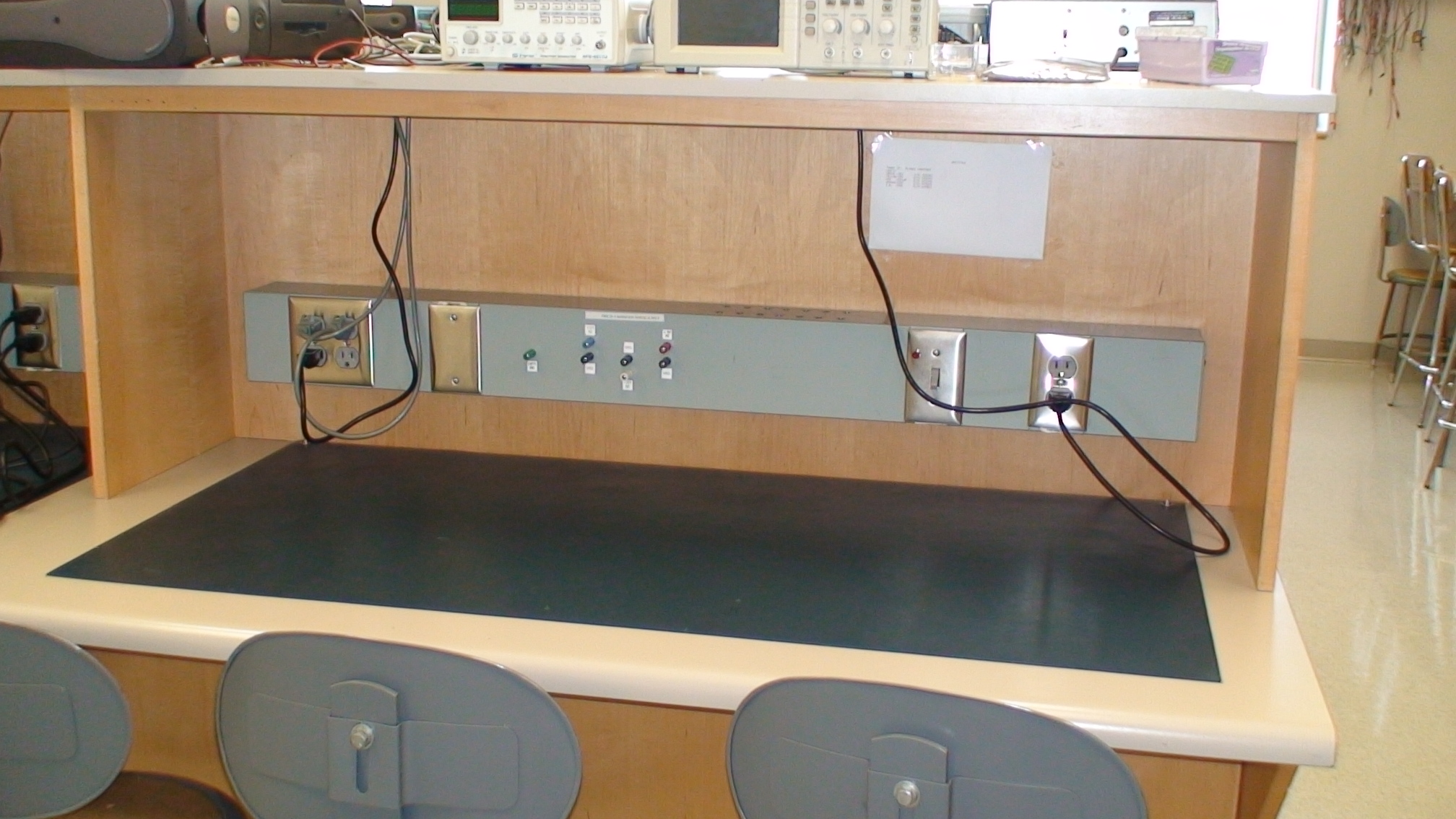
Each group will have their own permanent lab workstation. At the workstation you will do all your wiring and debugging for the course. Your workstation provides you with the power supply with ranges 5V, +12v, -12V and ground for your circuit. You will use the alligator cables to connect power and ground to your circuit.
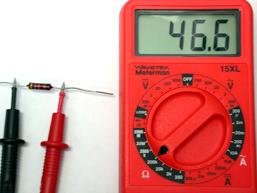
You will use the digital multimeter in the labs mainly for two tasks, for resistance measurement
and for continuity test.

The Continuity test checks electrical continuity between two contact (wired) points in your circuit.
1. Turn off power to your circuit.
2. Set the Function/Range switch on DMM to .
3. Connect the black test lead tip to one of the contact points and the red test lead
point to the other contact point.
5. The internal beeper emits a tone when resistance is between 0 and 400 Ohms.
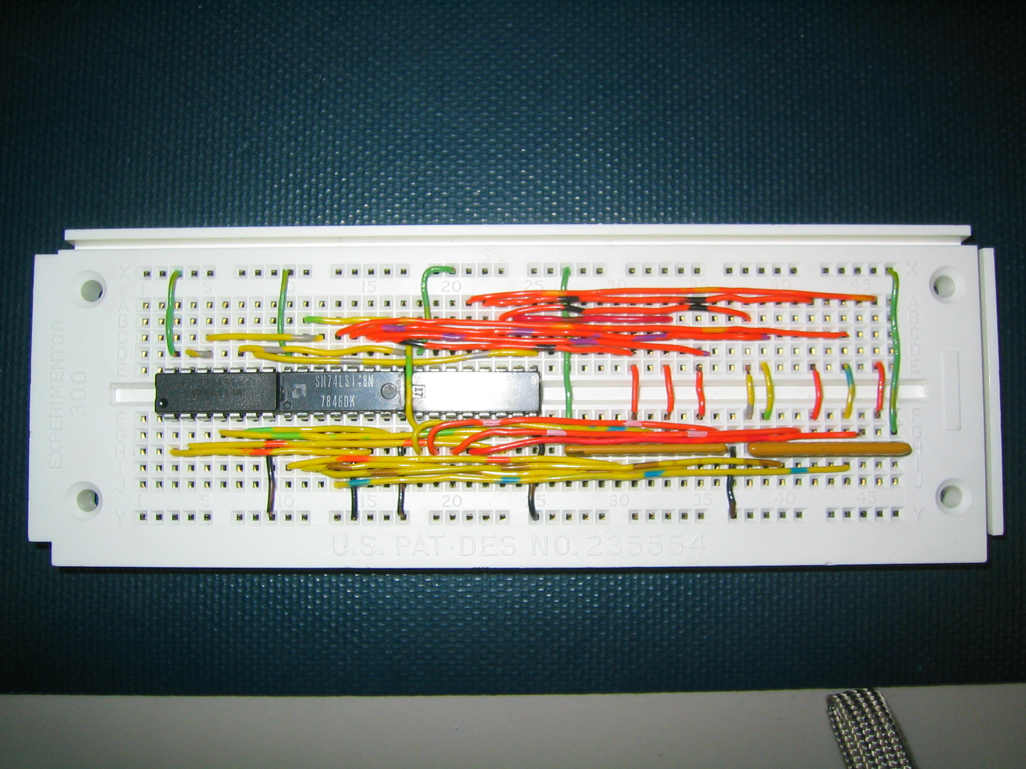
You will use a breadboard (as seen in the figure below) to construct and test digital circuits.
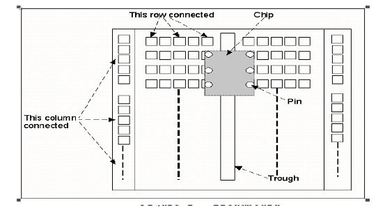
Holes on the breadboard are connected electrically in rows, except for the 2 columns down the sides. These rows are separate from each other, and each row is connected internally. Most of the breadboard consists of parallel rows of 5 holes each, separated by a trough from similar sets of holes. Each set of 5 holes is internally connected. By placing an integrated circuit (IC for short or a chip) over the trough, each pin of the chip can be accessed by 4 holes. The 2 columns are not connected to each other, but each column is connected internally for its entire length. This makes the columns useful for connecting to 5V and ground, for instance, since you will usually have several things to connect to each of these.
You are going to do a lot of wire cutting and wire stripping in PC/CP120. We will provide you with one wire cutter and stripper for each group.
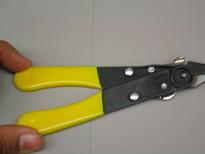
If you prefer to bring your from home you are welcome to do so.
- Cut wires to the length you need so they are nice and tidy on your board.
- Avoid poor connections! If you don't expose enough of the conductor (less than 3mm) you may have a
poor connection, or none at all, when it is inserted in a hole.


![]()
Wilfrid Laurier University
© 2019 Wilfrid Laurier University