Pages created and updated by
Terry Sturtevant
Date Posted:
May 12, 2017
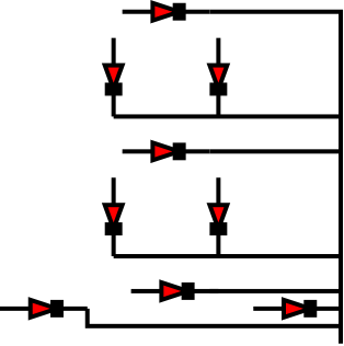
In the figure is a 7-segment display.
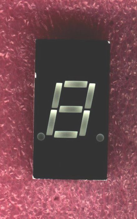
The segments are labeled as follows:
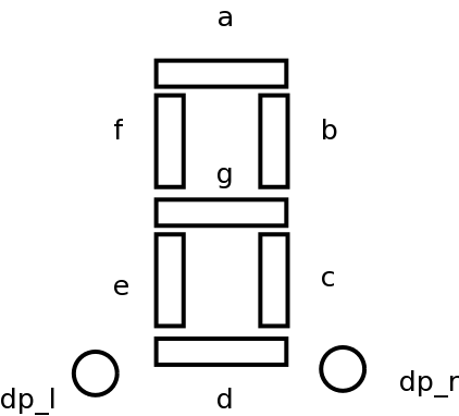
(Note that the diagram actually has two decimal points as well, so there
are
technically nine segments. One or both decimal points may be included.)
These segments
are individual LEDs,
labeled a to g, and can be turned on individually, or
all controlled by a BCD to 7 segment decoder.
The decoder takes a 4 bit BCD input, and has 7 outputs corresponding
to the display segments. It will assert the correct signals for the
segments based on the input.
There are two types of displays;
common anode
and
common cathode.
The distinction is whether the inputs need a "high" or a "low"
to turn on.
In either case, since each segment of the display is an LED, you
need to use
resistors on the segments
just as you would for discrete LEDs. Otherwise you will probably
destroy the device when you try to use it.
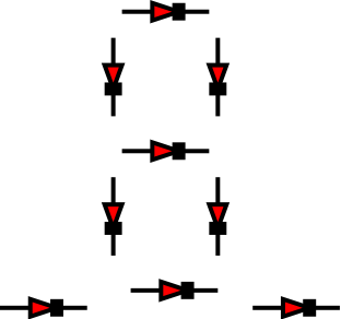
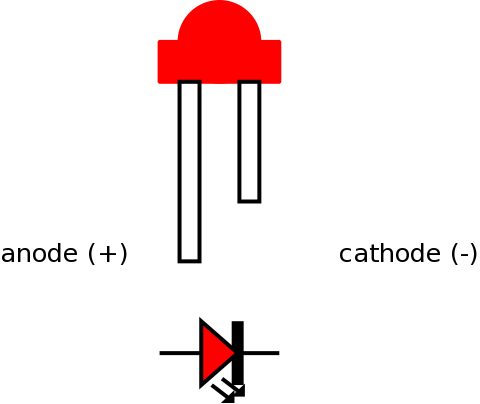
Here is a reminder of how the pins on an LED are identified:
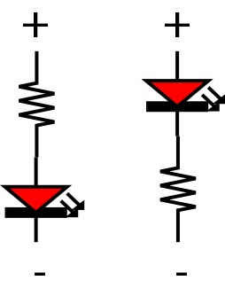
The resistor can be put either before or after an LED, as long as the
current flows in the right direction.
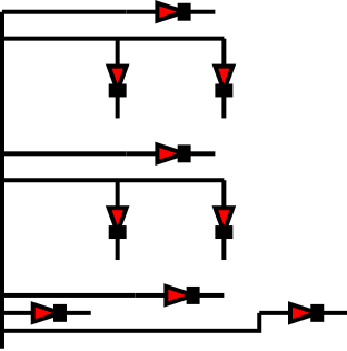
Since all of the LED segments are connected to the common pin, you could
use a single resistor between the common pin and power or ground,
(depending on whether the display is common anode or common cathode),
to limit the current to all of the LEDs. The only drawback with this is
that you might notice the display is dimmer when more segments are on.
(Hint: If you choose to use individual resistors, you can
use the resistors to connect the
decoder to the display, instead of having wires to connect the
decoder to the resistors and wires to connect
the resistors to the display
then you will
save a lot of wiring.)


![]()
Wilfrid Laurier University
© 2019 Wilfrid Laurier University