
Output
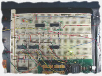
Circuit
The outputs from the EPLD are as follows:
- intalarm1
(internal speaker - slow beep)
- intalarm2
(internal speaker - medium beep)
- intalarm3
(internal speaker - fast beep)
- extalarm1
(external speaker - slow beep)
- extalarm2
(external speaker - medium beep)
- extalarm3
(external speaker - fast beep)
- lights1
(external green light flash - slow pulse)
- lights2
(external yellow light flash - medium pulse)
- lights3
(external red light flash - fast pulse)
The EPLD outputs either a high or a low voltage. Our problem with this is that this alone will not flash an LED
or make sound with a speaker. We decided to use a binary counter (74LS193)
and set it up in free running mode in order to make our LEDs flash. We input
the least significant bit from this counter to an AND gate (74LS08)
with the lights3 from the EPLD and tied the output to the red LED. This
meant whenever the lights3 was high, the red light would flash
(01010101...). The same was done with the next least significant bit and the
lights2 output to make the yellow LED flash (00110011...). Lastly, this was
done with the lights1 output and the next least significant bit in order to
make the green LED flash (00001111...).
Sample
of flashing frequencies

The speakers require very high frequency in order to
make an audible sound. We chose approximately 1 KHz. We decided that we also
wanted the speakers to beep according to the intensity of the alarm. This
was achieved by ANDing the output from the EPLD with the high frequency from
the function generator and ANDing this result with the appropriate bit from
the binary counter as mentioned above.
|