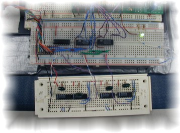
Input Condition Circuit

The inputs to the EPLD are as follows:
- distance
(4 bit binary number reading the 10's of inches)
- msd
(4 bit binary number reading of the 100's of inches)
- clk
(input clock pulse at 10Hz)
- car_on
(high if car on, low otherwise)
- car_moving (high if car is
moving, low otherwise)
- clkcount
(half the frequency of clk; taken from the second least significant bit
of the binary counter)
It was necessary to work with the output from the
Polaroid sensor in order to make it suitable for the EPLD. The sensor has
only one 4 bit binary output that feeds each digit; the 1's, 10's and 100's.
There are three active low clock pulses that signal which digit is coming
out at any one time.
We needed to get these values into our EPLD, so we
used two input latches to read the appropriate values and hold them
until they changed. We first inverted the active low clock pulse
for the 100's digit and fed that new clock pulse into the pin on the latch that would enable the inputs. This way, the inputs were only enabled when
the pulse is high, meaning only the 100's digit value would be output from
that latch. The latch holds its value until the inputs change when activated.
This did however present a problem. The clock pulse
that enabled the latch was a little longer than the pulse for the data, so
our output for the 100's digit would change at the end of the activate pulse
and read data intended for another digit. We solved this problem by
introducing two one-shots for each input clock pulse (two for the
100's pulse and two for the 10's pulse since both experienced this problem).
The clock pulse that we wanted would be shorter than the original one, start
after the original one started and end before the original pulse ended. The
first one shot took the pulse and compressed it horizontally as shown below.
The next one shot took that wave and delayed it so
it would start when the wave from the previous one shot ended. We fed this
new pulse into the latch so that it would only read the data for the desired
digit and not overlap.
DS2 Input Waveform

|