Pages created and updated by
Terry Sturtevant
Date Posted:
May 12, 2017
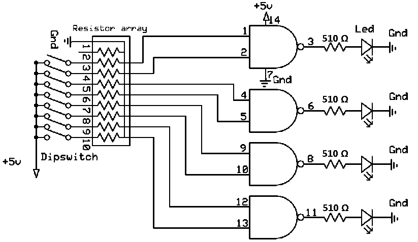
A Dual Inline Package, or DIP switch can be used to select between 0 and 5 volts at some point in a circuit. Since the dip switch does not have any power or ground connectors this must be done externally.
In our case we want a high (5V) when then switch is turned on, so each input pin we are using must be connected to power. When the switch is off we want a low (0V); but remember when the switch is off it is in a floating state. To resolve our floating pins issue we need to add a resistor to the output pins. Since we are using 8 switches, using 8 individual resistors would be rather tedious, so it is fortunate that we have a device called a resistor array which makes this convenient. The particular resistor array (10x-1-102) which we will use has several resistors in it which all have one end in common. In our circuit we connect the common pin of the resistor array to ground.
Light Emitting Diodes, or LED's for short, emit light when an electric current is passed through them. The amount of current must be limited, however, or the diode will be destroyed. Usually a current of 10 mA is sufficient to light a diode, so if a 5 volt supply is being used, a 500 resistor placed in series with the diode will provide the right current. Note that the diode has one long pin, called the anode, and one short pin, called the cathode. The longer pin is connected to the higher (i.e., more positive) voltage, and the short pin goes to ground.
For this lab we will be using the 7400 Quad NAND gate IC. This chip contains four 2-input NAND gates. The pin numbers associated with each input and output of this chip are listed above the input and output of the NAND gates in the diagram above. You can also find the pin and operating specifications on the datasheet.
In this lab you will create a circuit which will turn an LED (light emitting diode) on or off depending on the selected input. The LEDs will give a visual indication of a 1 (LED lighted) or a 0 (LED dark). We connect the DIP switch to select between 1 (high voltage +5v) and 0 (low voltage).

Demonstrate your results to the lab demonstrator.


Wilfrid Laurier University
© 2019 Wilfrid Laurier University