
Pages created and updated by
Terry Sturtevant
Date Posted:
May 12, 2017
In PC/CP120 labs we'll walk you through wiring a simple gate circuit using one specific integrated circuit (IC) the 7400 chip.
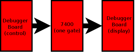
You'll use a debugger board for input and output.
It's a good introduction to some of the more complex logic
chips that you'll be using later in the lab.
The 7400 device is part of the 74xx family of
integrated
circuits.
(The xx refers to the fact that there are many possible
numbers which follow the 74.)
For more info about the 74xx family
see the 7400
series entry in Wikipedia.

Locate the 7400 chip/IC in your lab kit. This chip has SN74LS00N written on it. Note that there are 5 parts to the chip "number":
Normally you will just refer to the device by using the two sets of
numbers, such as 7400, and ignore the letters.
The LS tells you that it is a
low power Schottky chip.
The manufacturer includes other information along with the 74LS00
on the chip.
This is a Dual-Inline Package (DIP), referring to the chip's
two rows
of pins.
Notice that this chip has fourteen pins. If you want to use an IC chip,
then you will always need to know the pinout. That's electrical engineering
lingo for describing the way the pins are connected to the internal circuitry
of the chip. You need to know where the power supply is connected and
where the gate inputs and outputs are connected.
How do you know the IC pinout? You will need to look at the IC's datasheet.
The manufacturer provides you with the IC datasheets
for all of their products. See
7400 datasheet for an example.
Here's the
74-series IC data sheet index
Here's a picture of the 7400 chip in a circuit board:

and here's the pinout for a 7400 chip:
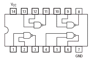
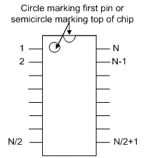
How do you know which pin is "pin 1" on the IC? You will find either a circle marking the first pin or a semicircle marking the top of chip. The pins on an N-pin DIP are numbered as shown :
 .
.
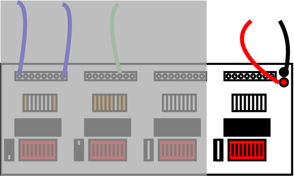
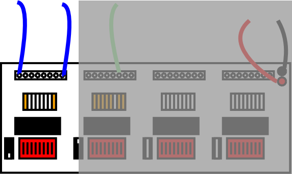
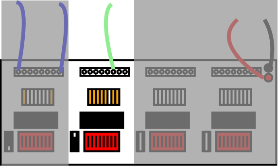
The output of a NAND gate should be HIGH unless both inputs are HIGH. (This is the opposite of an AND gate where the output should be LOW unless both inputs are high.) The animation below illustrates both of these.

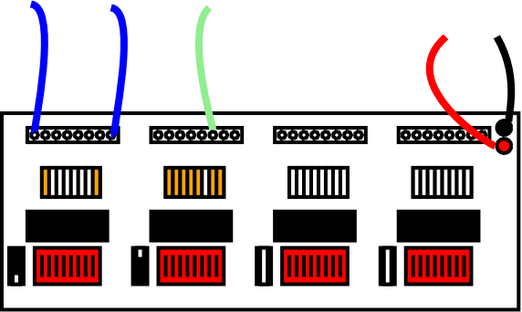
Demonstrate and explain your results to the lab demonstrator.


Wilfrid Laurier University
© 2019 Wilfrid Laurier University