PC/CP320 Physical Computing
Voltage, Current, and Ohm's
Law
Objectives
- To understand the importance of GROUND in a circuit
- To measure voltage using a digital multimeter
- To measure current using a digital multimeter
- To understand applications of Ohm's Law to series and
parallel circuits
- To understand how the difference in resistor values impacts
series and parallel circuits
Preparation
|
Ohm's Law
the voltage (or potential) across a
resistor is proportional to the current flow through
the resistor
|
V = IR , where
- V is the voltage across the resistor in Volts,
- R is the value of the resistor in Ohms, and
- I is the current flow through the resistor in Amperes
(Amps).
|
Equipment
- digital multimeter, bench power
- battery, Variable DC supply
- breadboard
- various resistors: 10kΩ (2), 20kΩ,
100kΩ
- deconstructed 9V battery
Procedure

|
This lab requires the use of a DC power supply. The lab
supervisor will review the bench supply configuration before
the start of the lab.
Keep the power OFF while
you are wiring your circuit and when you are making changes
to your circuit.
|
-
Basic Voltage Measurement
Measure the DC voltage of the 5V bench supply.
- Measure the DC voltage of the 7.2V battery.
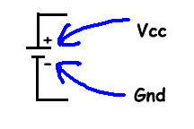
- Now connect one terminal of the meter to the positive
terminal of the 7.2V battery, and the other
terminal of the
meter
to the GROUND of the bench supply. What voltage
do you
read? What
is going on?
- Now add a connection between the negative terminal of
the battery and the
GROUND of the bench supply. What voltage do you read?
Explain what is going on to the lab
instructor.
- Now connect one terminal of the meter to the positive
terminal of the variable DC supply, and the other
terminal of the
meter
to the negative terminal (NOT GROUND) of the variable DC supply.
Adjust the
supply to produce 5V out. What voltage do you read?
- Now leave the one terminal of the meter connected to the
positive
terminal of the variable DC supply, and connect the other
terminal
of the
meter
to the GROUND (NOT NEGATIVE) terminal of the variable DC supply.
Leave the
output adjusted to produce 5V out. What voltage do you read? What
is going on?
Explain what is going on to the lab
instructor.
-
Resistors in Series and Parallel
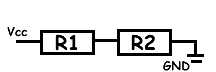
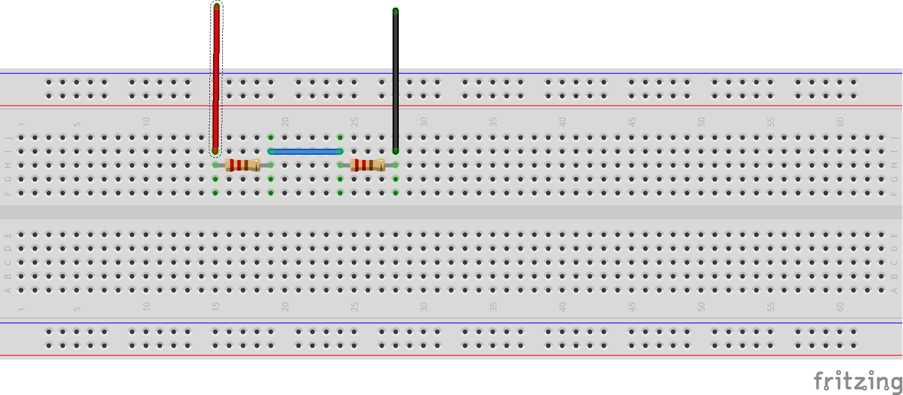
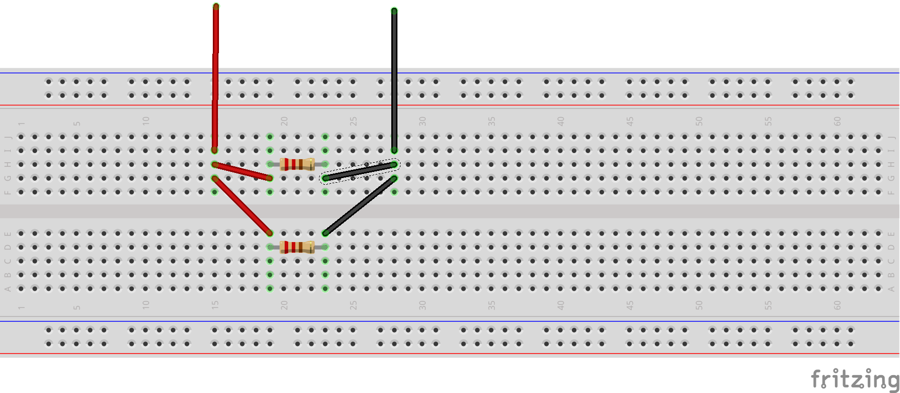
Construct a circuit with two resistors in series:
- Take two 10 kΩ resistors and measure their actual
resistance.
- Construct the following circuit, R1 =
R2 =
10
kΩ.
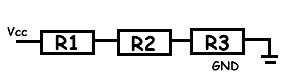
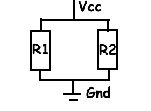
Note
that this circuit can be drawn two different ways (shown
below).

- Before connecting power, measure the resistance across
the two resistors together.
- Connect power, Vcc = 12 volts, and ground using
the
bench
supplies, and then turn on the power. If you have done this
right, nothing exciting should happen. If something
exciting happens, e.g. smoke or burning smell, immediately
turn off the power and get help from the lab staff.
- Measure the voltage across each resistor and the two
resistors in combination:
- Read
Measuring
DC Voltage.
- As shown in the diagram below, measure the voltage across
R1. What happens if you reverse your voltmeter
leads -
place
red probe where the black probe was and the black probe where
the red probe was? What is the relationship between your
probe position, the measured value, and the power and ground
locations in the circuit?
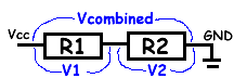
- Measure the voltage across R2.
- Measure the voltage across R1 and
R2.
- What is the relationship between the Vcombined
and
the
individual voltages? Was your probe placement consistent
across all measurements?
- Using Ohm's Law, calculate the currents I1,
I2,
and
Icombined.
Demonstrate your skill at measuring voltages to the lab
instructor.
-
Current Measurement
Now you are going to measure the current flowing
through each
resistor.
| |
Always measure
current IN SERIES with the load.
NEVER measure current across a voltage
source.
|
- Read the information about
preparing for current
measurements
.
- Read
Measuring DC
Current.
-
Read the section about preparing for current
measurements again.
- Note carefully, that a current measurement
requires
that the meter be in series with the load. In other
words, to measure current the meter must be part of the
circuit. Make sure power is off when you are modifying
the circuit.
- Note also, that when measuring current, the
red lead
is connected differently at the meter as compared to the
other measurements (resistance, voltage,
connectivity)..
- Improper use of the meter when measuring DC
current
can destroy the meter ... hence all the cautions and
notes.
- If you are not sure that you have understood the
instructions, have the lab staff check your hook-up before
you power up the circuit for the first measurement.
- You have to change the circuit to place the meter in
series with the load. Does it matter if the meter is before
or after the resistor (the load)? Test this by measuring the
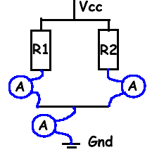
current at the three locations shown in the diagram below.
Notation: the circle with an A
inside is the symbol for an
ammeter.
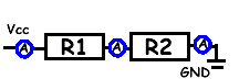
If you wire the circuit as in the following diagram, then the
ammeter can replace each wire in sequence for each of the measurements.
Understand that you will modify the circuit three times to
take the three measurements.
- How do the measurements compare to the calculations you
did in the previous step?
- What did you learn about the currents in a series
circuit?
Demonstrate your skill at measuring current to the lab
instructor.
-
Series and Parallel Circuits
For the two resistor series circuit, change R2 so
that R2
= 2
x R1 = 20 kΩ (approximation is OK). Measure
the
actual
resistance of R2 before building the circuit. Measure
the
voltage
across each resistor and the resistors in combination. Calculate
or measure the currents through each resistor and the resistors
in combination. [You notice that I prefer to measure voltage and
calculate current. Why?]
- Modify the series resistor circuit, so that R2 = 10
x R1
=
100 kΩ (approximation is OK). Measure the actual resistance
of
R2. Measure the voltage across each resistor and the
resistors in
combination. Calculate or measure the currents through each
resistor and the resistors in combination.
When you have resistors in series, does the larger or smaller
resistor dominate the circuit?
Does this relationship hold for three resistors as shown below?
How would you test this? Demonstrate to lab
instructor.
- Construct a circuit with two resistors in parallel as shown
below. Let R1 = R2.
- Measure the voltage across R1, across
R2,
and
across
R1
in combination with R2. Remember, take one
measurement at
a
time.
- What is the relationship between the individual
resistances and the total resistance?
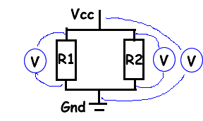
- Measure the current through R1, through
R2, and
through
R1 in combination with R2 as shown in
the
diagram
below.
Remember, take one measurement at a time.
- What is the relationship between the individual currents
and the total current?
If you wire the circuit as in the following diagram, then the
ammeter can replace each black wire in sequence for each of the
measurements.
- Repeat your measurements for R2 = 2 x R1
and
for R2
= 10
x
R1. When you have resistors in parallel, does the
larger or
smaller resistor dominate the circuit?
Does this relationship hold for three resistors in parallel? How
would you test this? Demonstrate to lab staff.
-
Voltages in Series and Parallel
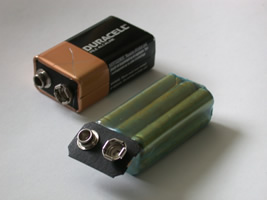
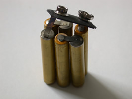
A 9 volt battery is actually constructed from six 1.5 volt
batteries as shown below. Are the 1.5V batteries connected in
series or in parallel? Show the calculations. [Lab staff will
have a deconstructed 9V battery so you can see how they do it ...
after you have figured out the connectivity.]
Unless you know a battery is composed of a set of encapsulated
batteries, it is not a good idea to cut batteries
apart.
-
Self check: Did you learn anything doing this
lab?
- An ammeter (current meter) is always installed in series
with a load in the circuit. Since you don't want the
measurement to affect the operation of the circuit, should
the ammeter behave like an open circuit or a wire (a short)?
Does the ammeter have a high internal resistance or a low
internal resistance? Explain.
- A voltmeter is always used in parallel with a load in the
circuit. Since you don't want the measurement to affect
the operation of the circuit, should the voltmeter behave
like an open circuit or a wire? Does the voltmeter have a high
internal resistance or a low internal resistance?
Explain.
Wilfrid Laurier University
© 2019 Wilfrid Laurier University


