PC/CP320 Physical Computing
Zener Diodes and Photodiodes Lab Requirements
Objective
A photodiode is used in a manner which is very similar to that of a Zener diode, so it makes sense to study them together.
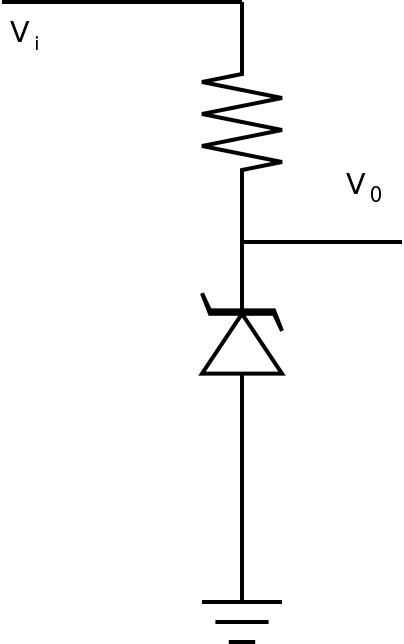
- to wire up a Zener diode as a voltage reference
- to use a photodiode in a circuit
Equipment
- bench supply, digital meter
- breadboard, resistance substitution box
- other components as required by the design
- one of each:
Procedure
Remember that both Zener diodes and photodiodes are usually wired in reverse-bias.
- Read Checking Diodes,
and test the zener diode
in forward and reverse
directions. Could you tell which direction was forward biased by
measurements alone?
Demonstrate and explain diode checking to the lab instructor.
- In the datasheet for the Zener diode, look up the zener
voltage and rated current for the device you have.
Calculate the resistor required for a voltage divider using the 12V bench supply.
Wire up the circuit according to your calculations and measure the output voltage.
Demonstrate your results to the lab supervisor.
- Connect the photodiode to a voltmeter. You should see a
voltage which changes with the light falling on it. This is
photovoltaic mode of the photodiode. Consider
the
direction of the voltage to represent forward bias for
the photodiode.
You might not know that an LED can operate like a photodiode. Try the same thing you just did with an LED.
- Check the datasheet to find the photocurrent for the
photodiode.
Calculate the resistance needed for a 12V supply which should provide a 5V change with light for the specified photocurrent.
- Now wire up the photodiode in series with a resistor close to
what you just calculated using the 12V supply.
Remember to apply power and ground so that the photodiode is in
reverse bias.
Measure the reverse voltage as you switch between light and dark. What change in reverse voltage do you get between light and dark?
Demonstrate your results to the lab supervisor.


