PC/CP320 Physical Computing
Resistors and Ohmmeter Lab
Objectives
A resistor is an analog component that
is used in most electronic circuits. Before we can put resistors to
good use, it is important that you understand how to recognize,
identify, and measure a resistor. The objectives for this lab are:
- To identify fixed resistors and determine their nominal
value, tolerance, and expected resistance range.
- To measure the actual resistance of fixed a resistor using an
ohmmeter.
- To understand the operation of a
potentiometer or variable resistor.
Preparation
Read the section on lab
notebooks on this web site. Record all data for this lab in
your lab notebook.
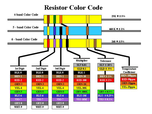
Read the section on fixed
resistors on this web site. The following charts may also be of
use; they all contain the same information but in slightly
different formats.
Note: If a resistor has only 3 bands, treat it like a 4 band
resistor with no tolerance band. The tolerance for 3 band resistors
is 20%.
Equipment
- digital multimeter - Wavetek 33XR assumed
- 1 4-band colour coded resistors (beige/brown body) of your
choice
- 1 5-band colour coded resistors (blue body) of your choice
- one of the above resistors should be less than 75 Ω
- trimmer and small screwdriver, any value
- boards with surface mount resistors, at least one per
group
- mini magnifiers, one per group
Procedure
Resistor Identification
For each of the following sections, record
resistor markings and required information in your lab
notebook.
-
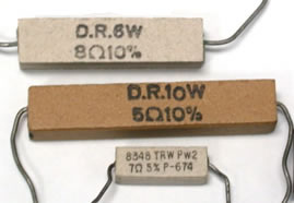
| The resistors to the right are higher power
resistors. Since the resistors are physically large, the
nominal value, tolerance, and wattage are written on the
resistor. Complete the table. |
 |
| |
nominal value |
tolerance |
wattage |
|
top resistor
|
8 Ω |
±10% |
6 Watts |
|
middle resistor
|
|
|
|
|
bottom resistor
|
|
|
8348 = part number
TRW = manufacturer
PW= wattage prefix
|
-
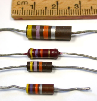
[click image to get a larger image] |
The resistors to the left are carbon composition (3)
and carbon film (1). Which one is the carbon film?
How did you determine that? [Note: carbon composition
resistors are obsolete.]
These resistors use the 4-band colour code to code the
resistor's nominal value and tolerance. For the
4-band code, the resistor is oriented so that the right
band is always gold, silver, or missing. Complete the
table.
Of the three carbon composition resistors, which resistor
has the highest Wattage? How can you tell?
|
| |
nominal value |
tolerance |
expected range |
| top resistor |
|
|
|
| middle top |
|
|
|
| middle bottom |
|
|
|
| bottom resistor |
47 kΩ |
± 10% |
42.3 kΩ - 51.7 kΩ |
-
On the bottom resistor, it is difficult to tell if the
second band is blue or violet. I have assumed that the band is
violet because yellow-blue-orange is not a valid combination
for a resistor with a ± 10% tolerance. Why are some
colour
combinations not valid?
-
Resistance Measurement
If you need to know the actual value of the resistor (not the
nominal value) or if the colour coding is too difficult to read,
it may be necessary to measure the resistance using an ohmmeter,
a DMM (Digital MultiMeter) or a VOM (Voltage/Ohm/Milliammeter).
The DMM and VOM (analog version of DMM) are multifunction meters
that have an ohmmeter function. Read
Measuring
Resistance
for
instructions on using the DMM as an ohmmeter before
continuing.
Before using an ohmmeter for the first time, determine the
meter's symbol for overload. NOTE: depending on the
function of the meter, "overload" may or may not be
dangerous to the meter. For the ohmmeter function, overload is
considered a normal output that indicates an open circuit. An
open circuit means that two points are not connected.
To determine how the meter will indicate overload:
- You can look up the symbol in the
Operator's
Manual. Look it up.
- Alternatively, if you don't have a copy of the
manual, use an open circuit to show an overload. Set
the meter to ohmmeter (any range) making sure the probes are
not touching anything (including each other) and observe the
display.
- For your meter, what is the overload symbol(s)?
-
|
|
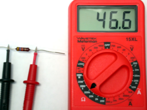
For the example shown to the left, the resistor is
yellow-violet-orange-gold which corresponds to the nominal
value 47,000 ± 5%. The expected resistance range is
calculated to be 44.65 kΩ to 49.35 kΩ. A
measurement
range of 200K is selected because the nominal value
of 47
kΩ is between 20KΩ and 200KΩ. Measuring
the
resistance
shows 46.6 on the display with the measurement range at
200K which means the actual resistance is 46.6
kΩ. |
For each of the resistors provided for this lab:
- determine the nominal value,
- determine the tolerance,
- calculate the expected resistance range, and
- measure the actual resistance.
Leave space in your table for the true resistance range
(next question).
Until you are completely comfortable with the interpretation of
the ranges, check the resistor across all of the ohmmeter range
values, starting at the lowest range, and record the display at
each range value.
Demonstrate resistance measurement to the lab
supervisor. Be
prepared to explain the associated terminology [e.g. nominal
resistance, tolerance, expected resistance range, actual
resistance].
Look over the lab so far:
Is there a single point of useful information that
would be good to include in a lab summary? If so, highlight it.
-
Variable Resistors
A potentiometer or variable resistor is
like a pair of resistors in series
with variable values but a fixed sum. The diagram on
the left shows the symbols for a potentiometer. The diagram on
the right (hopefully) makes clear the relationship between a
potentiometer and the two resistances R1 and
R2.
(Note: Sometimes a potentiometer is
also called a "trimmer".)
The total resistance of the potentiometer, R1 +
R2, is constant.
The arrow represents a slider or knob which will vary the values
of R1 and R2 subject to the constraint that
the total resistance
does not change.
Note: It may be easier to do these measurements by plugging
the potentiometer into a breadboard.
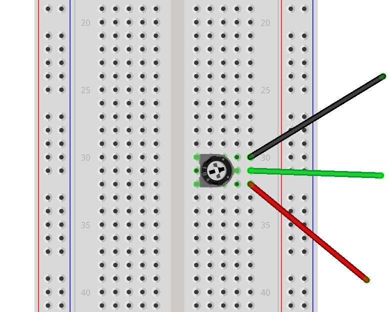
Use an ohmmeter to study the resistance of the
(unconnected) potentiometer. Correlate your observations with the
diagram above. Determine the minimum and maximum values of
R1, R2, and R1+R2.
Do the resistances R1 and R2 vary linearly
with the adjustment of the wiper?
- Note the numbers on the potentiometer.
(Note: There are usually two numbers; one of the numbers is a
lot number for the manufacturer, and the other indicates the
component value.)
How do they indicate
the resistance of the potentiometer? Is it similar to anything
else you've seen?
-
Problems with Resistance Measurement
When measuring a very small resistance, it is important to
account for the resistance of the meter's leads. Measure the
resistance of the leads by touching the two probe tips
together.
- In the instructions for using the digital multimeter, you
were cautioned not to include yourself as part of the circuit.
[Do not touch the component or the probe tip with your hands
as your body's resistance will affect the measurement.]
Measure your resistance and that of your partner.
- Make sure you are not grounded (e.g. are not touching the
case of any electronic device, are not using a static mat
strap) and that you are not part of a circuit.
- Place the meter on the lab bench.
- Stand away from the bench and gently grasp one probe tip
in each hand between your thumb and forefinger or gently
press the probe tip into the pad of a finger or palm. How you
hold the probe will affect the measurement.
- Have your partner select the appropriate scale. It will
be very difficult to get a single stable measurement; you
will have to take a visual average
How does the measurement change if the contact points on your
hands are moist? Resistance will vary from person to person
based on the percentage of body fat (fat has a higher
resistance) and on their internal hydration (water is a better
conductor). This is the principle behind body composition
analysis scales and meters.
-
Continuity Testing
Use the audible continuity tester mode on the resistors from
earlier in the lab. In theory, a resistor should not appear as an
electrical connection. What are your results? Why?
Can you determine what threshhold resistance is
required in order to not identify as a short circuit?
A continuity test is actually testing resistance. Therefore,
if you do not have a continuity tester, you can use an
ohmmeter to test continuity, by looking for a resistance
close to zero.
-
Surface Mount Resistors
Circuit boards use surface mount resistors, which are
too small to use colour bands. However, they are labeled in a
way that should be understandable once you understand colour
codes.
Take a circuit board with surface mount resistors from the
sample box and a mini magnifier. This investigation will be
easier if the SMT resistors are physically larger; easier to read
the numbers and easier to do the measurements. Note the board
number - written number in silver on the front or back of the
board. Find 2 to 3 resistors of different orders of magnitude.
For these resistors, record the resistor identification number
that is silk-screened on the circuit board [should start with the
letter R], the number as written on the resistor, the nominal
value of the resistor as determined by you, and the actual value
of the resistor as measured by the DMM.
Note: the nominal value may not match the actual value. There
are three possible reasons for a mismatch.
- You determined the nominal value incorrectly.
- You measured the actual value incorrectly.
- _________________________________________
-
Look at the image below.
|
For the image to the right, list as many resistor
values as you can. Write down:
- the resistor identification that is silk-screened
on the circuit board,
- the number on the resistor,
- the nominal value of the resistor.
R72 doesn't follow the normal 3 or 4 digit
numbering convention. What is R72 and why is it
used?
|
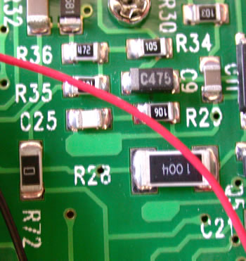
[click image to
get a
larger image] [Photograph
of the circuit board inside a DMM similar to that used in
this
lab.]
|
- Before you leave the lab, have the lab supervisor sign
your lab notebook immediately after your last entry.


