PC300/PC319 Final Project - Stepper Motor
Group: Shannon Kaye and Eduardo Barrenechea
Date Last Modified: 03-12-2001
Our project, was to control a stepper motor using a joystick. The exact specifications set out for the project as detailed on the web site are as follows:
Objective: Design and construct a circuit to control a stepper motor with a joystick.
Specifications: The system should use the value acquired from the joystick to control the speed and direction of the motor.
If the joystick is less than +/-5% from the center of its range the motor should not move.
If the joystick is to the right of centre, the motor should be driven clockwise.
If the joystick is to the left of centre, the motor should be driven counterclockwise.
If the joystick is 5% from center the motor should turn at one revolution every ten seconds.
If the joystick is at either end of its range the motor should be driven at 4 revolutions per second.
Between these extremes the motor speed should depend linearly on the position of the joystick.
Components: stepper motor, joystick, ADC, CPLD, op-amp.
Background:
To understand the scope of the project, one would need to understand the components that were needed to get the project functioning properly. These would consist of the following:
Joystick: Also important to the user is the joystick that he/she will use to control the stepper motor. The 'innards' of the joystick consist of two potentiometers, that, according to the movement of the joystick will slide back and forth, causing various voltage levels to be produced. These voltage will eventually, after being sent through more digital and analog devices, control the motor.
Operational Amplifier (Op-Amp): The operational amplifier, as it's name would imply does exactly that: it amplifies it's input providing a 'stronger' output. It will always act on a voltage, and in this case acts on the voltage provided by the joystick. It is needed in this case since the output voltage of the joystick is so minimal, that it would not have an impact, not even be registered by the ADC.
Analog-Digital Converter (ADC): The ADC, or analog to digital converter, is used to take an analog signal such as a voltage or current level, and convert it to a useful digital signal. In this case, the output voltage of the joystick is used as the analog input to the ADC, and it outputs and 8-bit digital output. This output is sent to the CPLD for further logic.
Complex Programmable Logic Device (CPLD): The CPLD simply allows vast amounts of logic and chip lay=outs to be held on one large board. The analysis of the 8-bit ADC output takes place here, as does some clock adjustments, and a few other logical operations that the end user need not concern themselves with.
Stepper Motor: Ultimately, the most important part of our project to the final user. It is the part that would be used to perform an operation of some sort. There are four (may be more/less in other stepper motors) coils inside the motor. Each of these can have a current sent through them, producing a magnetic field around it, which will turn the stepper motor slightly in one direction or another. If you stimulate the four coils in the right pattern, then you will get the stepper to move around in 'steps' (hence it is called a stepper motor).
Basic Approach/Circuit Description:
The approach that we took to the project as should be noted, was not exactly according to the standards set on the web page. Due to some difficulty in getting the a proper clock division code working in VHDL, and some hardware problems, little time was left to endure rigorous coding. This means that the relationship between joystick position and the stepper motor's spped of rotation was not linear (ie: the motor didn't increase with EVERY change in the joystick's position). Instead, we set three cases. The first is when the joystick is positioned at +/- 5% from the center. We gave this position a certain speed of rotation. The second case involved is when the joystick is positioned at an extreme, and this was given a second speed of rotation. In the middle, everywhere in the middle, exists the third case, and this was given the third and final speed.
It must be noted that in our case, it was found that the extreme left on the joystick yielded some strange voltage due to the calibration of the joystick, and so when coding the cases, we assumed that the user would not move the joystick to this extreme and so left 'set' (in our VHDL) our left extreme in reality somewhere in the middle of the range. This is not to say that this position caused no movement in the stepper, it most certainly did. All this means is that the speed did not necessarily follow our convention. The output voltage of the joystick at this position did in fact lie within the parameters, we just could not predict where, and so the speed varied whenever the joystick entered this range.
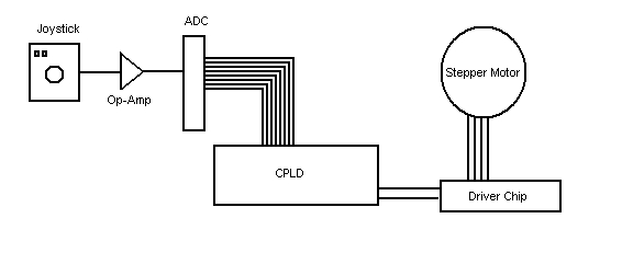
Block Diagram:
The basic layout of the components, as detailed indirectly above is the following:
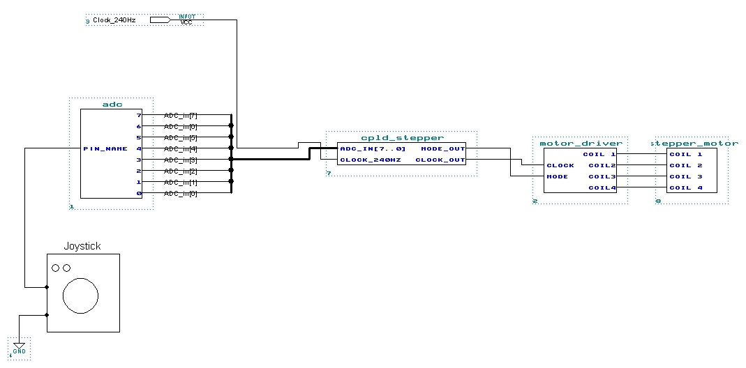
Design Specification:
The design specification is a highly detailed structure of the functioning final product. It involves the chip numbers (ie: type of chip), the pinouts, and the lay-out of the chips too. The following is the design specification:
Timing Diagram:
The following is a pictorial display of how the CPLD will perform as a function of time. The outputs are based directly on the inputs and sothey will change accordingly. Click on the following link to download the MAX+PLUS II timing diagram for our stepper control.
Timing Diagram
Structured Logic Device Description:
The structured logic device description is what lies behind the CPLD. It is the logic that the programmer has created, and programmed into the CPLD for use for the specific purpose of solving the problem that has been handed to them. In our case, the problem is that of getting the stepper motor to work with the joystick's position. So, we will take the various inputs from the ADC (which actually represents the position of the joystick) and examine/analyze them, and consequently perform some logic on these data values to get a suitable output. Click on the following link for the VHDL code used to program the CPLD:
VHDL Code
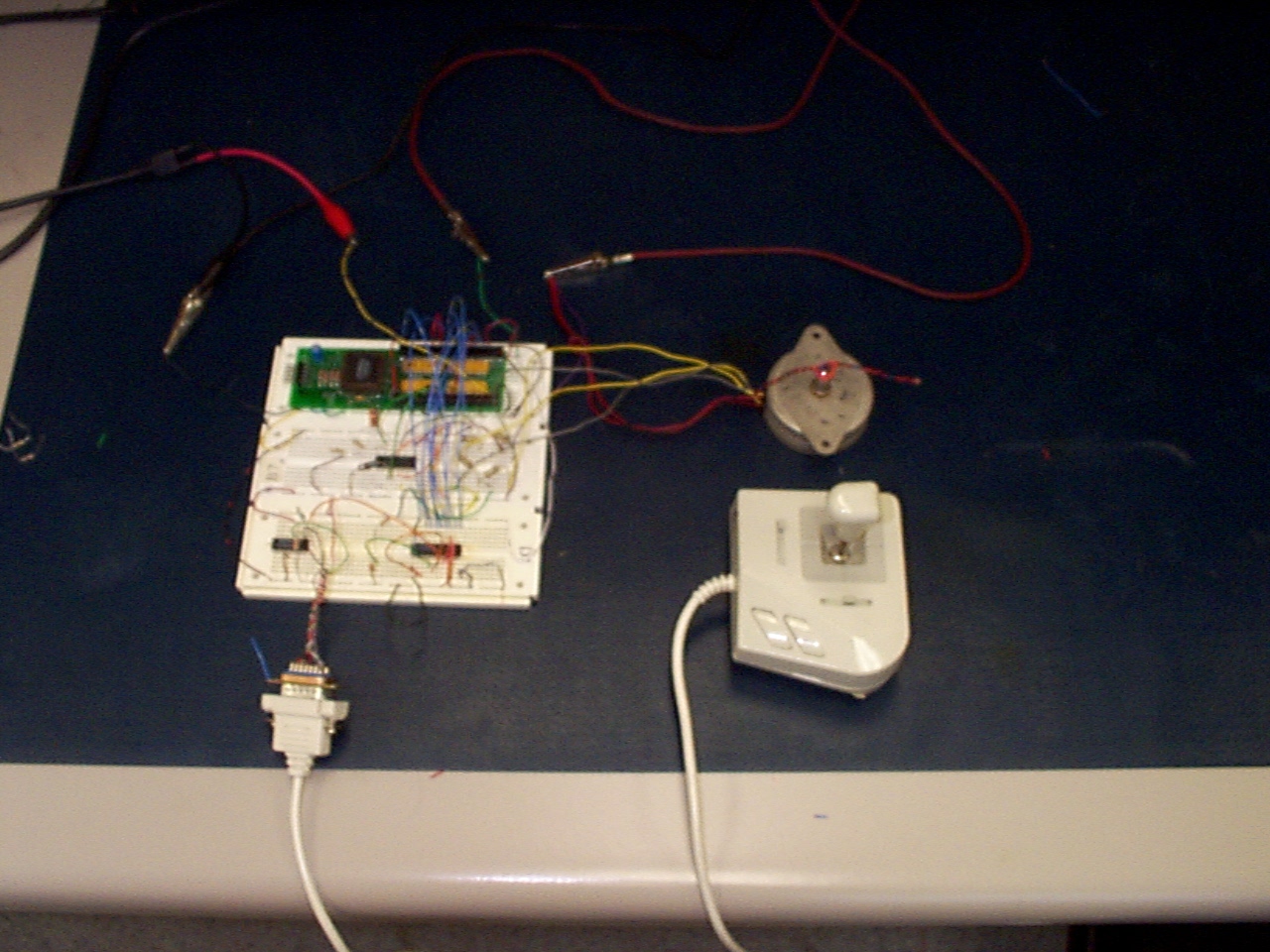
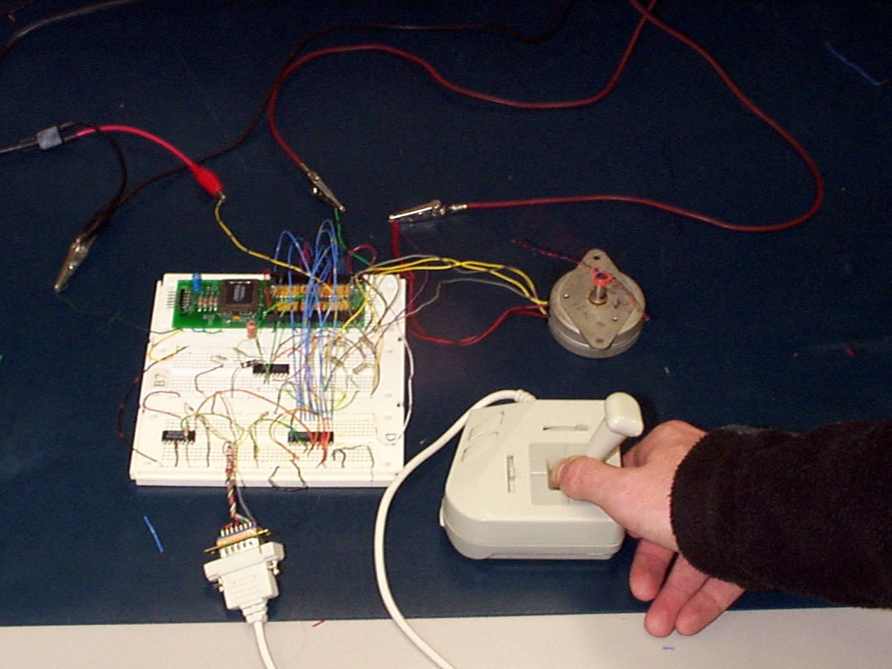
Last but not least, here are two pictures of our project after the arduous journey to completion.