
Group:
Jeremy Raymond, raym4480@mach1.wlu.ca
Przemek Kunka, shempyy@hotmail.com
Specifications:
Basic security system with standard features. Ability to arm and disarm the system after entering the correct password. Ability to alter password when in disarmed state. Display indicators of armed state, disarmed state, triggered sensors and delay.
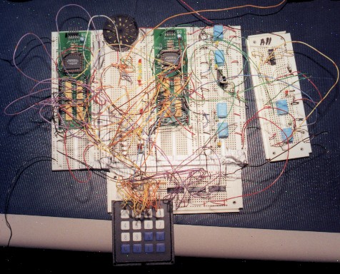
Components:


The delay logic is a basic counter. When it gets the start delay signal it counts for a specified amount of time. Once that time has expired it outputs the delay done signal until it receives the reset signal.
When the correct pasword is entered and the arm signal is received the system delays for the specified amount of time in the delay logic. Once the delay is over the system goes into the armed state. When one or more sensors are tripped the system goes again into a delay state and once the delay is over into the alarmed state where the buzzer sounds. A corresponding diplay light is on depending on which sensor triggered the alarm. In any state the system may be disarmed and retured to the disarmed state by entering the correct password and pressing enter.
The password_get logic is a basic register. When a key is pressed on the keypad it is converted to a binary code. This code is stored in the first part of the register. Subsiquent key strokes are converted and entered into the register beside the existing codes. The register can hold up to four inputs. Once this limit has been reached subsequent codes being entered will loop back to the front of the register and overwrite the existing value. Sending the clear signal resets the register to all zero values.
The password logic goes from the password not entered (idle) state to the password ok state when the key_input coming from the password_get logic is equal to the current_pass (which is all zeros when the system is first initialized. The system returns to the idle state when reset_get is asserted (from main logic) Similarly it enters the bad password state when the key_input is not equal to current_pass. This is reset to the idle state when the clear siganl is asserted. The programing state 1 is entered when the password signal is asserted. If key_input is equal to the current password and enter is pressed the system goes into the second programming state. From here if a new password is entered and the clear and enter are asserted at the same time then a new pasword is set and the system returns to the idle state. To exit the programming state without changing the password clear is asserted.
Note: Pressing the clear button before pressing enter when entering a password allows re-entry of the password. Pressing clear while in the programming mode will exit programming mode.