CONTENTS | PREV | NEXT


5 Troubleshooting DAC and ADC

5.1 Testing Digital-to-Analog Converters

The basic testing of a DAC is illustrated in Figure 1 below.  From the debugger board the connections are made to the DAC inputs from line 0 to 2n - 1 where n is the number of bits.  The binary inputs are applied to the inputs and the output is an analog signal which is observed with a meter.  

The ideal output would be a straight-line stair-step.  To have an ideal output, the increase bits in the binary code must be increased, thus the approximation is improved.  In addition the number of discrete steps increases, hence the output results a straight-line linear ramp. 

5.2 D/A Conversion Errors

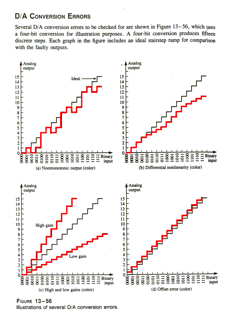
Diagrams from chapter 13 of Digital Fundamentals, T. L. Floyd, Prentice-Hall.


Non-monotonicity: The step reversals in Figure A indicate non-monotonic performance, which is a form of non-linearity. In this particular case, the error occurs because the 21-bit in the binary code is interpreted as a constant 0. That is, a short is causing the bit input line to be stuck LOW. 

Differential Non-linearity: Figure B illustrates differential non-linearity in which the step amplitude is less than it should be for certain input codes. This particular output could be caused by the 22 bit having an insufficient weight, perhaps because of a faulty input resistor. We could also see steps with amplitudes greater than normal, if a particular binary weight were greater than it should be. 

Low or High Gain: Output errors caused by low or high gain are illustrated in Figure C. In the case of low gain, all of the step amplitudes are less than ideal. In the case of high gain, all of the step amplitudes are greater than ideal. This situation may be caused by a faulty feedback resistor in the op-amp circuit. 

Offset Error: An offset error is illustrated in Figure D.  Notice that when the binary input is 0000, the output voltage is nonzero and that this amount of offset is the same for all steps in the conversion. A faulty op-amp may be the culprit in this situation. 


5.3 Testing Analog-to-Digital Converters

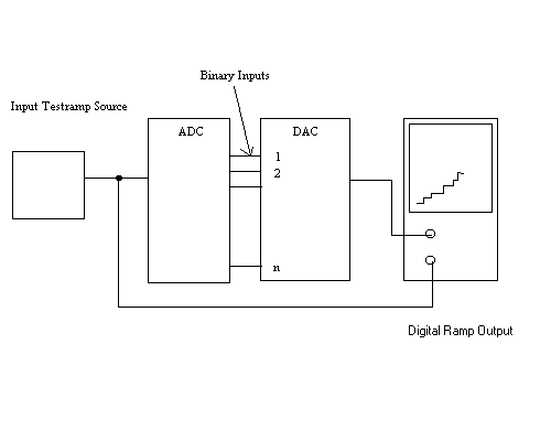
The basic testing of a ADC is illustrated in Figure 2 below.  In this instance a DAC is used to convert the ADC output back to analog (stair-step ramp) to compare it with the test input (linear ramp) which is applied to the input of the ADC.

5.4 A/D Conversion Errors

Again, a 4-bit conversion is used to illustrate the principles.  Let's assume that the test input is an ideal linear ramp.

Missing Code: The stair-step output in Figure 1 indicates that the binary code 1001 does not appear on the output of the ADC.  Notice that the 1000 value stays for two intervals and then the output jumps to the 1010 value.  In a flash ADC, for example, a failure of one of the comparators can cause a missing-code error.

Incorrect Codes:  The stair-step output in Figure 2 indicates that several of the binary code words coming out of the ADC are incorrect.  Analysis indicates that the 21-bit line is stuck in the LOW (0) state in this particular case.

Offset: Offset conditions are shown in Figure 3.  In this situation the ADC interprets the analog input voltage as greater that its actual value.  This error is probably due to a faulty comparator circuit.


CONTENTS | PREV | NEXT