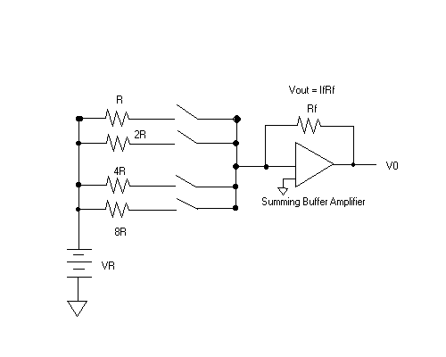
Figure 1 illustrates a weighted resistor Digital-to-Analog converter which has a reference voltage source, a set of binary-weighted resistors, an op-amp and a set of switches. From the diagram it can be noticed that each switch has it own binary bit of the digital input word which controls it. The switch is closed when the binary bit is 1 and open when the binary bit is 0. When the binary bit is 1 (switch is closed) the current flows through the resistor in series into the summing bus. When the current from all networks of resistors are summed in the amplifier, the total current is proportional to the output voltage of the amplifier.

Since the currents sum together and go through Rf where the inverting input is 0V and Vout = IfRf. The input resistors are inversely proportional to the binary weights of the input bits. The lowest-value resistor (R) corresponds to the highest binary-weighted input (23 = 8). The other resistors are multiples of R (i.e. 2R, 4R, and 8R) and the equivalent binary weight is 22, 21, and 20, respectively. The input current is proportional to the binary weights and the output voltage is proportional to the sum of the binary weights. This is because the sum of all the input current is through Rf.
The disadvantage of the weighted resistor DAC is the numerous resistor values. For instance, if we take an 8-bit converter, the 8 resistors will range from R to 128R in binary weighted steps. This type of DAC is very difficult to mass produce due to the range of resistors required where the tolerance is less than 0.5% to accurately convert the input.