PC/CP300: Electronics Laboratory II
Controlling Power
Objective
We have various output transducers whose power can be controlled using various techniques. The pairing of an output transducer and a control circuit is not limited to the ones you will be investigating; although some pairings make more sense than others. The specific objectives for this year are:
- to control the operation of a relay using a bjt
- to control the operation of a DC motor using an IRF510 power MOSFET
- to control the speed of a DC motor over a range of input signal values
Equipment
The items to be controlled were covered in the output transducer lab and may include:
- DC Motor
- Relay
- Clock Mechanism
- Peltier Effect Cooler
- Solenoid
The items to be used for power control may include:
- BJT -- 2N3904 (Fairchild Semiconductor)
- Power BJT -- 2N3055
- Power MOSFET
- IRF510 -- Fairchild, International Rectifier
- IRF9510 -- Fairchild, International Rectifier
- Relay local, Axicom V23105
- Relay local, Omron G5V-2
- optoisolator - 4N26 - Fairchild, Isocom
Procedure
Relay
Remember to put diodes across the coils of inductive devices to avoid back EMFs. (And think about which way the diode needs to go.)
-
Start by investigating the devices you will be using to do the power
control. Do only the devices assigned for this lab. Each of the
following device-specific links points to a series of questions and
tasks that you would normally want to do in order to understand the
device. It is assumed that you have completed the prelab.
- BJT : 2N3904
- Power MOSFET (N channel) : IRF510
- Look at your results from the previous lab where you used
the relay. What voltage was required to switch it?
Test this by using the variable supply and using it to switch the relay.
- Wire up an op amp as a buffer. Feed the voltage above into
the buffer
and use the output of the op amp to try and
control the relay. Does it work?
If it doesn't work, observe the voltages at the input and output of the buffer. How should they be related? Is that what actually happens?
What is the limitation of the op amp that prevents it from switching the relay directly?
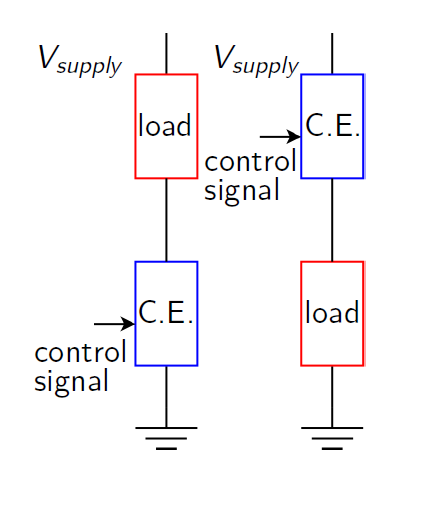
- Design and implement a circuit to turn the relay on and off using
the bjt.
- Now use your op amp buffer to show that the relay
can be switched with this new circuit.
How does this new circuit get around the op amp limitation you mentioned earlier?
Demonstrate and explain your findings to the lab supervisor.
DC motor
- Look at your results from the previous lab where you used
the DC motor. What voltage was required to make it run?
Test this by using the variable supply and using it to run the motor.
- Use the op amp buffer from above. Feed the voltage above
into
the buffer
and use the output of the op amp to try and
control the motor. Does it work?
If it doesn't work, observe the voltages at the input and output of the buffer. How should they be related? Is that what actually happens?
What is the limitation of the op amp that prevents it from running the motor directly?
- Design and implement a circuit to run the DC motor using the IRF510
power MOSFET.
- Now use your op amp buffer to show that the motor
can be controlled with this new circuit.
How does this new circuit get around the op amp limitation you mentioned earlier? Demonstrate and explain your findings to the lab supervisor.
- If your are finished early, start work on the postlab!


