PC221 Analog Electronics I
Simple DC Circuits
Objectives
- To review analysis of simple DC circuits.
- To review wiring and measurement of simple DC circuits.
- To introduce the use of SPICE circuit simulation.
- To compare results of analysis, measurement, and simulation.
Equipment
- digital multimeter, bench power, oscilloscope
- various resistors
Procedure
Setup
- Assemble the components for the following circuit:
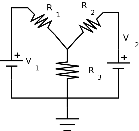
Use the following values:
- V1 = 5V (Use the bench supply.)
- V2 = 12V (Use the bench supply.)
- R1 = 2.7 kΩ
- R2 = 4.3 kΩ
- R3 = 1.2 kΩ
-
Measure
the resistor values and the supply voltages
using the digital
multimeter and
enter them in the Table 1:
| Table 1: Component Values |
| Quantity |
Measured Value |
Units |
| R1 |
|
|
| R2 |
|
|
| R3 |
|
|
| V1 |
|
|
| V2 |
|
|
- After you have filled in the table, construct the circuit.
Circuit Measurements: Digital Meter
Don't even think of trying to measure
currents unless you have reviewed how to measure current. Otherwise
you may destroy the meter!
(You can calculate all
of the currents instead from the values in the table above.)
-
Using the digital meter, measure V1 and V2
again, (in case they have changed under load), along with
the voltage at the top of
R3. Using these values, you can calculate the voltage
across each resistor as well as
the currents
through each resistor and supply.
Fill these values in the appropriate column of the table below.
| Table 2: Simple DC Circuit |
| Quantity |
Digital Meter |
Oscilloscope |
Simulation |
Analysis |
Units |
| VR1 |
|
|
|
|
|
| VR2 |
|
|
|
|
|
| VR3 |
|
|
|
|
|
| Isupply1 |
|
|
|
|
|
| Isupply2 |
|
|
|
|
|
| IR1 |
|
|
|
|
|
| IR2 |
|
|
|
|
|
| IR3 |
|
|
|
|
|
Show your results to the lab instructor before
continuing.
Circuit Measurements: Oscilloscope
-
Now measure each of the voltages in the circuit using the
oscilloscope.
Remember that oscilloscope leads are not the same as digital meter
leads. Specifically, the ground clip on each lead must
go to ground. You can't just put the two clips from one lead on
either end of a component.
When you need to measure the voltage across a component and
neither end is at ground, you can use the math functions on the
oscilloscope to subtract the voltage at one end of the component
from the voltage at the other end.
Make sure you have the same vertical scale on both
channels, or else your math will be wrong.
Make sure the two channel inputs are set to DC
coupling
for these measurements.
- Using the measured voltages, and the resistor values from
Table 1,
calculate each of the
currents.
- Fill in the results in the appropriate column of Table 2.
Circuit Simulation: Introducing operating point
analysis
SPICE is an
analog electronic
simulator. (You may have already used a
digital
simulator in PC/CP120.) It was originally developed in the 1960's
and is available in many different versions on many different
platforms. There are free versions and professional versions.
It's important to note that since the underlying algorithm,
SPICE, is the same, the results given by different versions should
be insignificant most of the time. (Some manufacturers have
modified the analysis, so there might be some minor differences.)
We'll be using one of the free versions. You can use either to do
this part.
LTspice Instructions
-
LTspice
is a PC based simulator, which is free to download and
install.
(If you want to
download it for yourself, you can.)
(Note: LTspice is a Windows program, but it runs on Linux under
Wine. Ask me if you want information about this.)
Follow the instructions
in the
Introduction to LTspice
to draw the circuit and do an operating point
analysis. This will
give all of the DC currents and voltages in the system.
Note: You'll be given the voltages of the various "nodes" in
the circuit; you'll have to figure out which node from LTspice
corresponds to which node in your own Kirchhoff's law analysis.
There will be a "netlist" file created by the simulator with this
information in it, in case you have trouble figuring it out.
Ground is always assigned as node zero.
Be sure to use your measured voltage and resistance values
from Table 1 in your
simulation, so your currents should be as close as possible to
their calculated values .
Open the netlist, and put the node numbers on your circuit diagram
in the appropriate places.
- Fill in your results in the appropriate column of Table
2.
- Now take one of the resistors in your diagram, disconnect it
from the circuit and rotate
it
180 degrees. Now put it back in the circuit. Rerun the
simulation,
and note the sign of the current through the resistor.
Is it the same as before?
What happened? (Hint: Look at the netlist again to figure out what
happened.)
-
Show your results to the lab instructor.
- Save your circuit and your LTspice files for future use.
CircuitLab Instructions
CircuitLab is a web-based
simulator. There is no software to install, and it runs in a
browser.
-
Draw the circuit and do a DC simulation. This
will
give all of the DC currents and voltages in the system.
Be sure to use your measured voltage and resistance values
from Table 1 in your
simulation, so your currents should be as close as possible to
their calculated values.
- Fill in your results in the appropriate column of Table
2.
- Now take one of the resistors in your diagram and rotate
it
180 degrees. Rerun the
simulation,
and note the sign of the current through the resistor.
Is it the same as before?
What happened?
(Hint: Every component has a default order to its pins, even when,
(like with a resistor), the order is practically irrelevant.)
-
Show your results to the lab instructor.
- If you create a (free) account on CircuitLab, you can save
your circuit for future use.
If your measurements and simulation agree, you should be pretty
safe doing the circuit analysis outside the lab. If that is the
case for you, the rest of the lab can be completed later.
Before you leave the lab, have the lab instructor
sign your lab notebook immediately after your last entry.
Analysis: Kirchhoff's Laws
It's always better to solve circuits
algebraically, rather than with specific values, so that you can plug
in
numerical values at the end. It makes mistakes easier to correct,
and
allows you to change component values easily without having to start
over from scratch.
- Use Kirchhoff's Laws to analyze the circuit.
Be sure to use your measured voltage and resistance values
from Table 1 in your
calculations, so your currents should be as close as possible to
their calculated values .
(Hint - if you use a spreadsheet for your calculations, it
will make it easy to change values later on.)
- Fill in the results in the appropriate column of Table 2.
Comparing results
- Compare the values from the actual circuit to the values from
your analysis above.
The important thing is to
rationalize your different results. In other words, if
any
two quantities differ by more than 20% or so, you should recheck
your various values because there is probably a mistake somewhere.


