PC/CP200 Electronics Laboratory I
Other Components
Objectives
- To understand the operation of a capacitor.
- To understand the operation of a diode.
Equipment
- digital multimeter, bench power
- breadboard, bare DIP switch
- various resistors (1kΩ, 3.3kΩ, 10kΩ),
capacitors
(10μF,
100μF)
** note polarity **, diodes, LEDs
Procedure
- Read Measuring
Capacitance, and check the capacitance of a
100 μF capacitor. Use this for
C1 below.
Demonstrate measuring capacitance to
the lab instructor.
- Construct the demonstration circuit shown below.
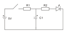
Use a 5V supply and a standard LED.
Let
- R1 = 3.3 kΩ
- R2 = 10 kΩ
- C1 = 100 μF
Close and open the switch a number of times. Notice that you
can see the time it takes to charge and discharge the capacitor
because the LED will light up and dim slowly.
You will be replacing various components in this circuit
with ones of a different value. I want you to observe the
change in charge and discharge times, if there is any.
- replace R1 with a 1 kΩ resistor. Does it
charge
faster,
slower, or the same? Does it discharge faster, slower, or the
same? Explain why.
- keeping the modified circuit, replace C1 with
10
μF capacitor. What happens to the charge and
discharge times? Explain why.
- Are the charge and discharge times a function of the
resistance in the charge/discharge path or a function of the
capacitance in the charge/discharge path?
Demonstrate and explain operation of this circuit
to the lab instructor.
- Replace the capacitor in the previous circuit with two
capacitors in series, as in the circuit shown below.
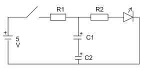
Use a 5V supply and a standard LED.
Let
- R1 = 3.3 kΩ
- R2 = 10 kΩ
- C1 = 10 μF
- C2 = 100 μF
When you have two capacitors in series:
- Does the order of the capacitors impact the performance
of the circuit?
- Does the smaller or larger capacitor dominate the
response of the circuit?
- A 10μF and 100μF capacitor in series provide a
total
capacitance of 9.1μF. What is the equation for combining
capacitances in series? (If the answer is not obvious, do the
next exercise and come back to this later.)
- Replace the capacitor in the previous circuit with two
capacitors in parallel, as in the circuit shown below.
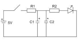
Use a 5V supply and a standard LED.
Let
- R1 = 3.3 kΩ
- R2 = 10 kΩ
- C1 = 10 μF
- C2 = 100 μF
When you have two capacitors in parallel:
- Does the order of the capacitors impact the performance
of the circuit?
- Does the smaller or larger capacitor dominate the
response of the circuit?
- A 10uF and 100uF capacitor in parallel provide a total
capacitance of 110uF. What is the equation for combining
capacitances in parallel?
Demonstrate and explain your results to the
lab instructor.
- Read Checking Diodes,
and test the diode and the LED in forward and reverse
directions. Could you tell which direction was forward biased by
measurements alone? Could you tell an LED from a normal diode by
measurements alone?
Demonstrate and explain diode checking to the
lab instructor.
-
Construct the demonstration circuit shown below, without the
diode. Observe the brightness of the LED. Measure the voltage
across the LED.
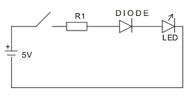
Use a 5V supply and a standard LED.
Let
- Add the diode to the circuit. Does the addition of the
diode affect the brightness of the LED? Measure the voltage
across the diode. Measure the voltage across the LED.
- Replace the diode with another LED. Does the addition of
a second LED affect the brightness of the original LED?
Measure the voltage across each LED.
- Explain your observations.
- Construct the demonstration circuit shown below. The switch
(use a piece of wire) can be at position A or at position B in
the circuit. Observe the operation of the circuit with the switch
at position A; then observe the operation of the circuit with the
switch at position B. Explain the operation of the circuit.
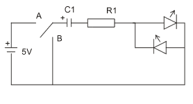
Use a 5V supply and two standard LEDs.
Let
Demonstrate and explain your results to the lab
instructor.
Before you leave the lab, have the lab instructor
sign your lab notebook immediately after your last entry.
Wilfrid Laurier University
© 2019 Wilfrid Laurier University


