CP316: Microprocessor Systems and Interfacing
Introduction to the Development Environment
(Simulator)
Objectives
Development Kits are small prototyping boards typically obtained from the
microprocessor/microcontroller manufacturer.
Software is developed on a microcomputer,
assembled, simulated and tested, and then downloaded to the target system
(development board).
- introduce the QwikFlash Development Board
- test the QwikFlash board using the pre-programmed performance
verification
program
- introduce the MPLABX IDE
- introduce the MPLABX IDE simulator
Equipment
- QwikFlash Development Board pre-programmed with the performance
verification
program
- development board power supply
- microcomputer with MPLABX IDE installed
Procedure
- Take the QwikFlash development board and it's power supply from the
hardware
kit.
- Test the board using the pre-programmed performance verification program.
Follow the procedure in
QwikFlash
Board Test .
The board test provides a simple way of testing most
components on the board.
At any point during the term, if you think there are problems with
your board,
use this program to test your board.
Demonstrate the board test to the lab
supervisor.
- Put away the hardware and lock up your cabinet.
- To program the board, you will use the MPLABX IDE to enter
assembly code,
build and assemble your project, then test your code with the built-in
simulator.
Today you will enter a very short assembly language program,
create a project, add the source code to the project, build and test the
code.
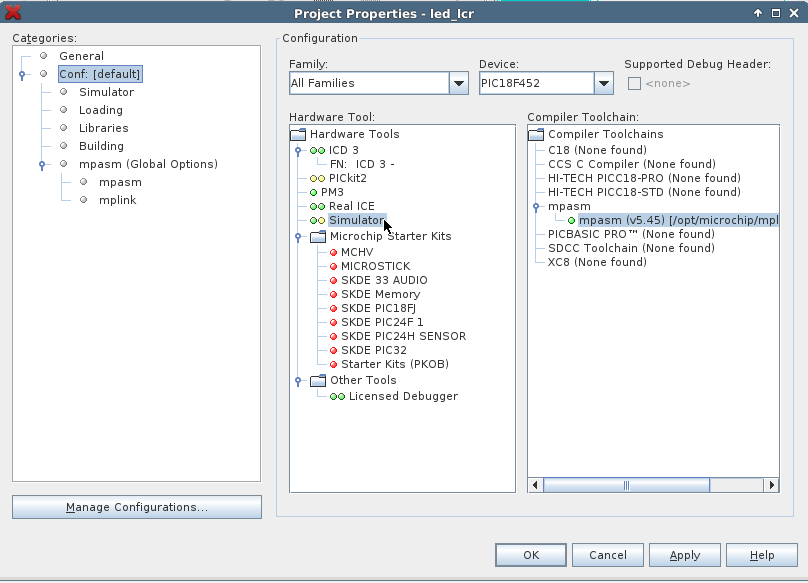
To use the simulator, follow these
instructions:
Stop the debugger if you have it running, and open
the Project
Properties menu. Select the simulator instead of the ICD3.
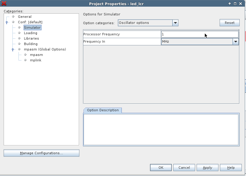
Once you've chosen the simulator, you can set the oscillator frequency
to 10 MHz
to match your board.
-
Take the program
test.asm ,
create a project, assemble
and run.
Notes:
- When entering code, if the tab spacing is not correct, use
Edit > Properties >
Sizes to get an appropriate spacing.
Demonstrate your familiarity with the IDE to the lab
supervisor.
- Every PIC processor has a set of device configuration bits that are set
only once when the device is programmed. To introduce you to the concept
of device configuration bits, you will watch a Device Configuration
eLearning
session from Microchip that was originally done for a different
type of 8-bit
PIC chip. Although a few of the details are different from our processor,
it is still relevant at the concept level.
- Device configuration bits can be defined in a number of ways:
- Device configuration bits can be set in the IDE after
selecting the device.
How would you set the device configuration bits using the IDE?
- Although the device configuration bits can be set in the IDE,
good programming
practice uses directives to set the bits at the start of the program so
that the configuration is always downloaded with the program.
This practice
makes clear your configuration expectations to anyone reading
the program.
- The User's Guide below shows how to use the new,
more readable, CONFIG format
for setting the device configuration bits.
- However, you may encounter code that uses the older
__CONFIG format.
- You should always use the new CONFIG format for your code as the older
format will cause warnings in newer versions of MPLAB.
- You cannot mix the CONFIG and __CONFIG directive formats in the same
program.
Take your existing program
test.asm ,
modify the
device configuration statements to the new style
in your existing project, assemble
and run.
NOTE: assembly programs are named
filename.asm but
they will be stored as filename.txt for readability from this
web server.
Use one of the following resources:
- PIC18F452 section from
PIC18
Configuration Settings Addendum [pdf,
350pp; ©2005 Microchip Technology Inc.] describes the
new CONFIG assembler
directives.
- Part 1, chapter 4, sections 4.11 and 4.12, in the
MPASM™
Assembler,
MPLINK™ Object Linker, MPLIB™ Object Librarian User's
Guide [pdf, © Microchip Technology
Inc.] describe the original __CONFIG format and
the new CONFIG assembler directives, respectively.
Demonstrate your configuration changes and the results of
the program
to the lab supervisor.
Wilfrid Laurier University
© 2019 Wilfrid Laurier University


