CP316: Microprocessor Systems and Interfacing
QwikFlash Development Kit - Board Test
[click on image to increase size] |
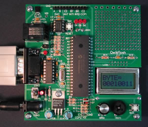
The QwikFlash Development Kit
comes pre-programmed with a performance verification program that lets
the user test all components of the board.
QFPV.asm - source for the
performance
verification program
|
To perform a test, apply power to the board using the provided 9V power supply.
The power supply provides 300 mA of current and connects to the QwikFlash board's
CON3 power jack via a six-foot (2,8 m) long cable with a 2.1 mm power plug
on the end.
- Immediately above the power supply connector, CON3, there is a power switch,
SW1, which turns the power to the board on/off. Turn the switch on.
- LED D1, the power indicator, to the right of the power switch should
be lit.
- LED D2, "alive" indicator, should blink (10 milliseconds
on) every 2.5 seconds for a 2.5 MHz internal clock (10 MHz oscillator).
- On the LCD, liquid crystal display, the top left entry should be
QFPV for QwikFlash Performance Verification.
- Locate RPG1, rotary pulse generator, and output LEDs D4 and
D5. Turn the RPG left and right. As you turn the RPG through its range of
motion, you should see the LEDs D4 and D5 light up to represent the binary
values 0 to 3. If you count the increments (where each increment is represented
by a different output), you should see 24 increments over a full revolution
of the knob.
- SW2, reset, resets the system. Position RPG so that both output
LEDs are on. Pressing reset should reset the system and the LEDs should go
off.
- The current temperature, as measured by the temperature sensor located
at TMP1, should be displayed on lower left corner of the LCD. If you carefully
blow on the sensor or lightly touch the sensor, the temperature should rise.
Any temperature above 125 degrees is incorrect.
- Locate SW3, an input switch, and output LED D6. Push SW3
to toggle the D6 LED. In addition, it will complement (one's complement with
the result displayed in hex) the value being displayed on the lower right
hand corner of the LCD.
- Turn POT1, potentiometer, to change the values being displayed on
the right of the LCD. The upper and lower values should be the same or the
complement of each other depending on the state of SW3. The lower value tests
the potentiometer value through the A/D converter on the microcontroller.
The upper value tests U2, the D/A converter, on the board.
Wilfrid Laurier University
© 2019 Wilfrid Laurier University


