CP316: Microprocessor Systems and Interfacing
Flashing LEDs using Delay Routines
Objectives
When using a new development board, the typical first program is one that turns
LED(s) on/off. LEDs are usually connected to bi-directional I/O ports and these
are the simplest peripheral interface on the board. The timing signal
controlling
the LED will be monitored using an oscilloscope driven from Port C.
- downloading code to the QwikFlash Development Board
- using the MPLABX programmer
- modifying the sample program to obtain alternate lighting patterns
- using C2 on the top header strip to allow the timing signal to be
measured on an oscilloscope
- setting up a project for the performance verification program
Equipment
- led_delay.asm - sample
program
to light the 'Left LED'
- led_delay2.asm - an
alternate
sample program to light the 'Left LED'
- QFPV.asm - source for the
performance
verification program
- QwikFlash Development Board
- MPLAB ICD3 hardware (unit, USB cable, target cable)
- PIC18FXX2
Data Sheet [pdf,
332pp; ©2006 Microchip Technology Inc.]
- oscilloscope
Procedure
The MPLABX programmer allows you to run code on the
target board, which will still work after the ICD3 is disconnected.
- Set up a project containing led_delay.asm,
a sample program to light the 'Left LED'. Set up a watch window containing
the three port A registers and the looping variables. Simulate the program
to make sure you understand its operation. Save the project.
-
Use the led_delay project from the previous
step to
learn how to use the ICD unit in both debug and programming modes.
(Use the
Debug menu to use the debugger, and the
Run menu to use the programmer.)
With the programmer, after the device is programmed you should be
able to disconnect the ICD3 and the program will run when the
Qwikflash board is turned on.
For
most lab demonstrations you will be using debug mode.
Demonstration - demonstrate both debug and programming modes on the
ICD unit.
- Start a new project. Modify the led_delay program to light the Left, the
Center, and the Right LEDs in sequence. Specifically, the sequence should
look like: Left LED on, all LEDs off, Center LED on, all LEDs off, Right
LED on, all LEDs off, and repeat. Only one of the LEDs should be on at any
time. Get it working.
Demonstration - demonstrate the operation of the above
program and be
prepared to explain your code.
- Start a new project. Modify the led_delay program to display the sequence:
all LEDs off, Alive LED on, Alive+Left LEDs on, Alive+Left+Center LEDs on,
Alive+Left+Center+Right LEDs on, and repeat. The sequence must start with
all LEDs off. Get it working.
The sample program used a CLRF to initialize PORTA. This works very
well for question 3 but is not the best choice for this program. What is
the problem? Suggest a better code sequence.
Explain why looking at the LED circuit schematics in the previous portion
of this lab was important to the operation of this program.
Demonstration - demonstrate the operation of the above
program and provide
requested explanations.
- Set up a project containing led_delay2.asm,
an alternate sample program to light the 'Left LED'. Get it working
on the board. Explain the difference between led_delay.asm and
led_delay2.asm. I
think led_delay2.asm uses a better approach. Explain why this program
is more flexible.
Demonstration - demonstrate the operation of the above
program and be
prepared to provide the requested explanations.
-
Now create macros to initiallize all of the LEDs, turn on and off
each LED individually and add them to your previous include file.
Modify your program to use this new arrangement.
Demonstration - demonstrate the operation of the revised
code.
- From the datasheet, identify all possible functions for each I/O pin on
Port C. Then, indicate which functions are possible when using the
QwikFlash
Development Board. Remember, once a microcontroller is installed in
a circuit,
the hardware configuration will potentially limit the multiple uses of a
port pin.
- For the TRISC register associated with Port C, indicate which pin
directions
are fixed (note the direction) by the QwikFlash hardware and which
are bi-directional.
- You will be using C2 on the top header strip to allow the timing signal
to be measured on an oscilloscope. What registers will have to be
initialized
to use Port C for this function? What will the initialization sequence
be?
Demonstration - explain the results of your investigation of
Port C and
its implementation in the QwikFlash environment.
- Using led_delay or led_delay2 as a base program, modify the code to allow
the signal that is driving the left LED to be displayed on the oscilloscope
(use the C2 pin). Measure and record the duration of the
on and off intervals.
Demonstration - demonstrate the use of the scope to measure
signal timing;
explain changes to the program.
- In the previous question, you used an oscilloscope to measure the on and
off times for the program that lights the left LED using a delay routine.
- Do the timing for the appropriate section of the program by hand to
prove that this time is correct. Give your result (a) in clock cycles
and (b) in seconds.
- Verify this by using the stopwatch option in the
simulator to
time the delay routine.
To use the stopwatch, you need to use the simulator for
debugging. Stop the debugger if you have it running, and open
the Project
Properties menu. Select the simulator instead of the ICD3.
Once you've chosen the simulator, you can set the oscillator frequency
to 10 MHz
to match your board.
Then you can choose the stopwatch from the
Window/Debugging menu.
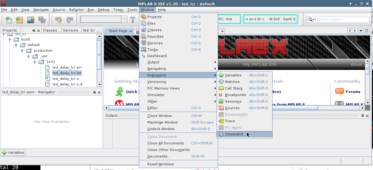
The stopwatch measures the time between breakpoints,
or you can single step
through the code to see the time for each instruction.
Demonstration - demonstrate the use of the stopwatch option.
Explain
your hand calculated timing. Comment on the respective
accuracy of the scope
vs hand timed vs stopwatch option.
NOTE: Some groups may find this question long.
Any material
not completed in the lab is homework.
- Set up a project containing QFPV.asm,
the source for the performance verification program for the
QwikFlash Development
Board. Download it to the board.
Test
the board. You should always have this program/project available. This
will allow you to test the board whenever you have any concerns about the
operation of the board.
Wilfrid Laurier University
© 2019 Wilfrid Laurier University


