Pages created and updated by
Terry Sturtevant
Date Posted:
May 12, 2017
A Dual Inline Package, or DIP switch can be used to select between 0 and 5 volts at some point in a circuit. Since the dip switch does not have any power or ground connectors this must be done externally.
If we want a high (5V) when then switch is turned on, each input pin we are using must be connected to power. When the switch is off we want a low (0V); but remember when the switch is off it is in a floating state. To resolve our floating pins issue we need to add a resistor to the output pins.
Here's an active high configuration. When a switch is closed, the signal will be connected to power. When a switch is open, the signal will be connected to ground through the resistor.
Note the signal comes from the same side of the switch as the resistor. I've only shown four connected to make it less cluttered.
Here's an active low configuration. When a switch is closed, the signal will be connected to ground. When a switch is open, the signal will be connected to power through the resistor.
Note the signal comes from the same side of the switch as the resistor. I've only shown four connected to make it less cluttered.
Since we are using 8 switches, using 8 individual resistors would be rather tedious, so it is fortunate that we have a device called a resistor array which makes this convenient. The particular resistor array (10x-1-102) which we will use has several resistors in it which all have one end in common. In our circuit we connect the common pin of the resistor array to ground.
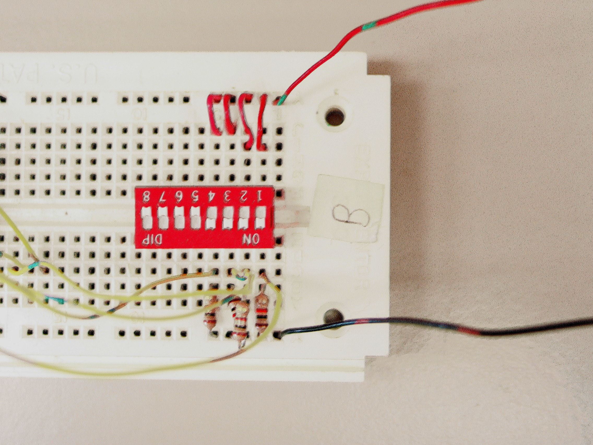
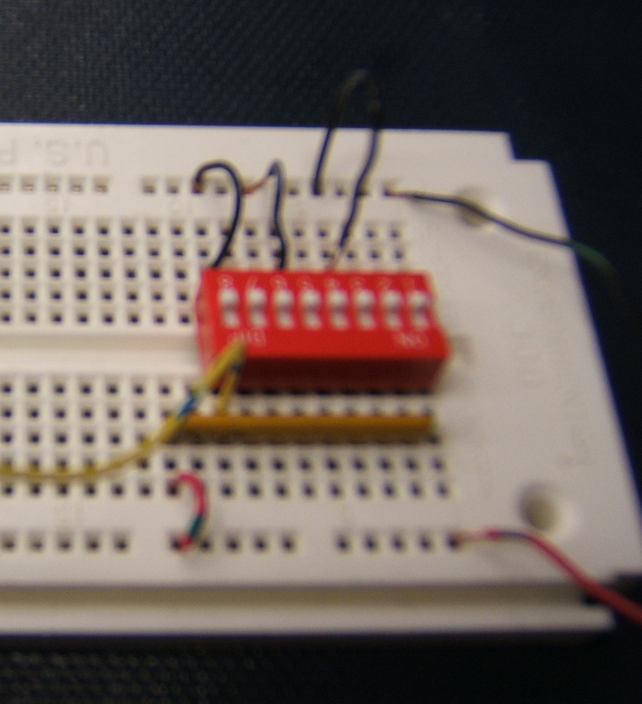
In the image below, the circuit is set up for active high operation, so that when the switch is closed, the output is high, and when the switch is open, the output is low. (Only a single signal is shown to avoid clutter.)
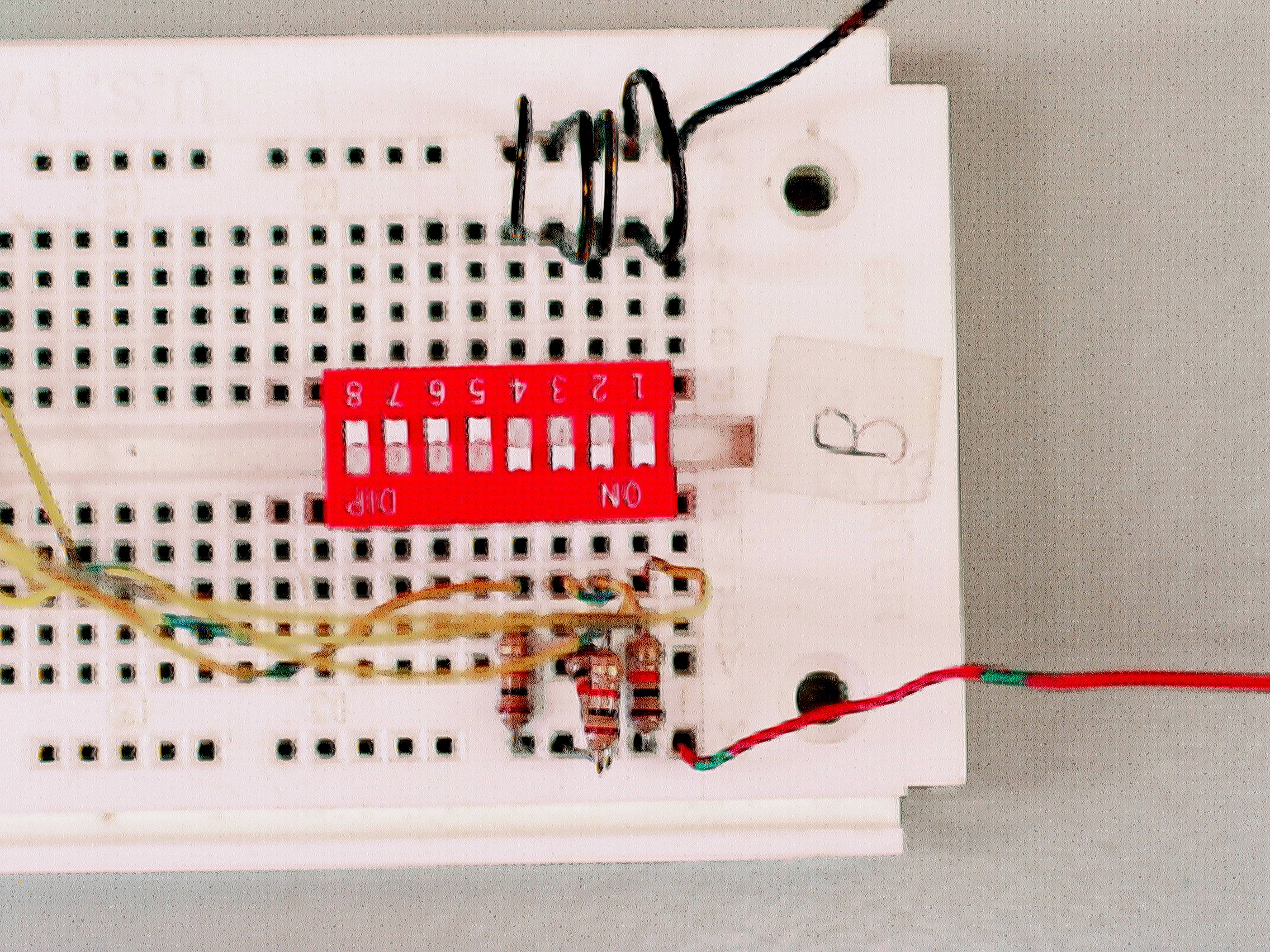
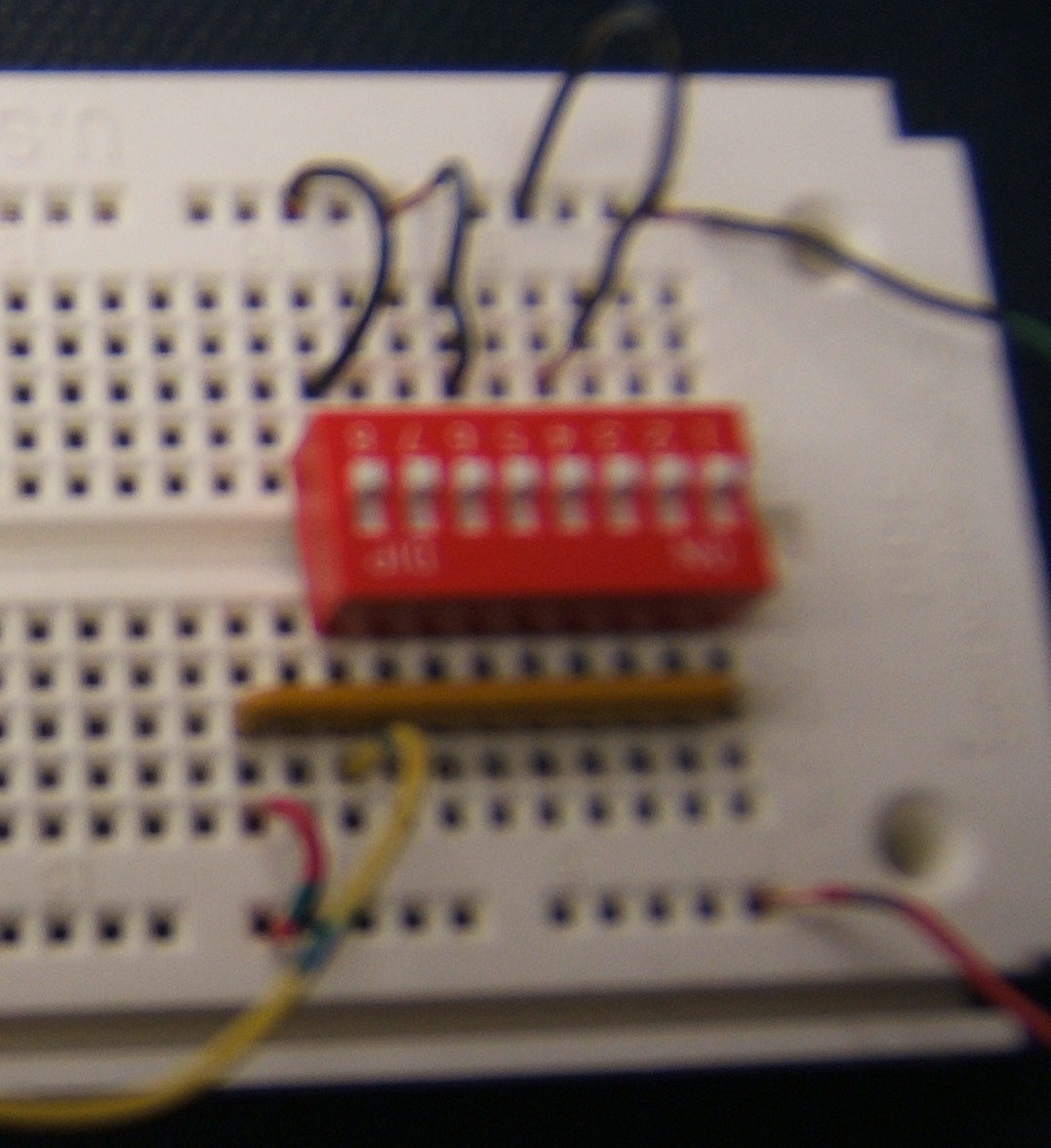
In the image below, the
cases have been reversed, so the
circuit is set up for active low operation, so that
when
the switch is closed,
the output is low, and when the switch is open, the output is high.
Note the
changes that happen in this case.
Usually it doesn't matter which switch position
(i.e. "on" or "off") gives a high,
so either setup is fine.
The output is taken from the side of the switch with the resistor array.
Since all of the points in a row are connected, the output can come from any place in the correct row.
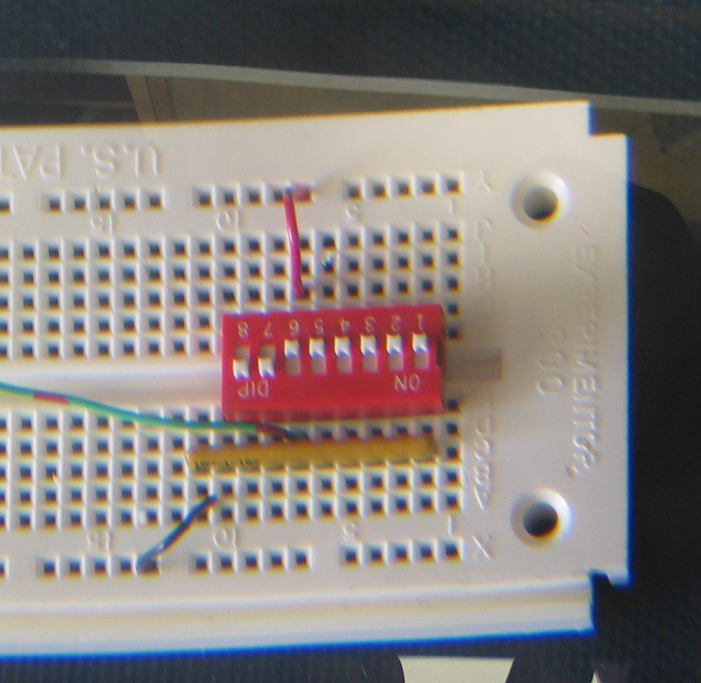
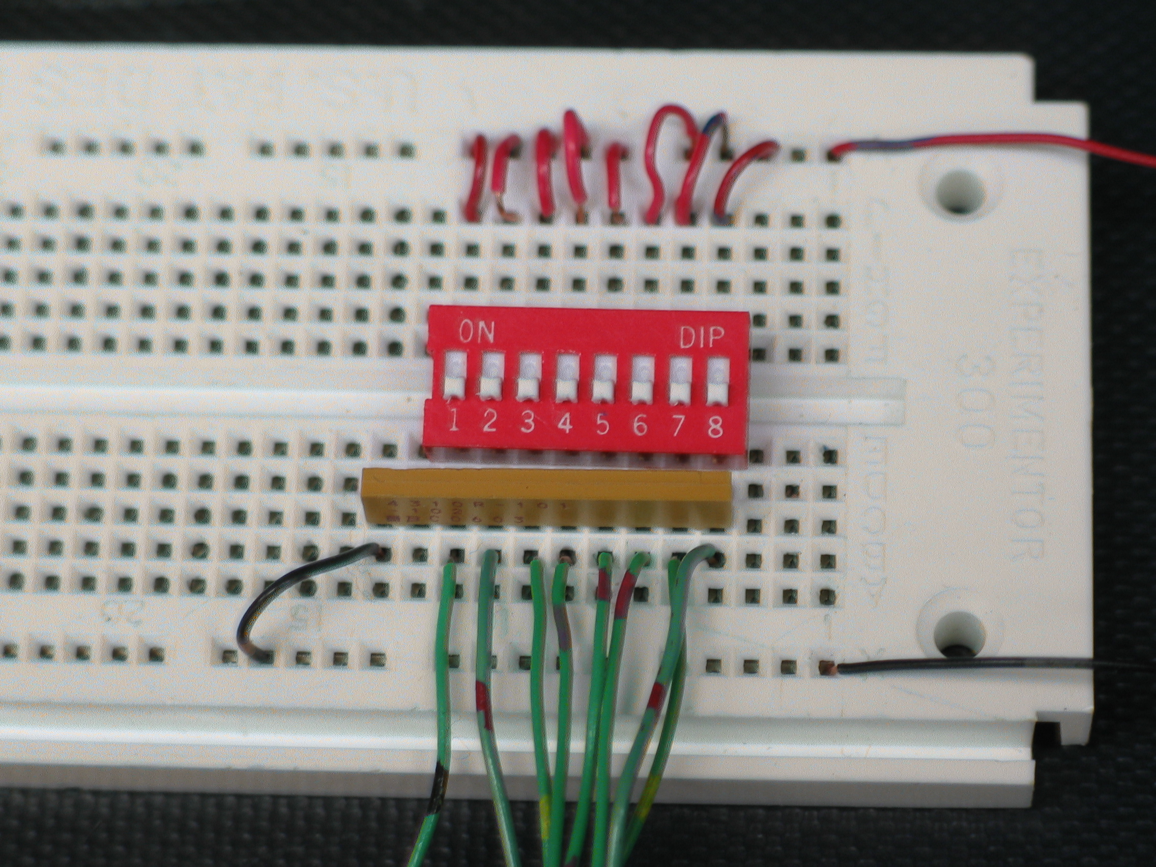
Here's the active high setup again, with all of the
switches connected.
The green wires are the signal wires coming from the
switches.
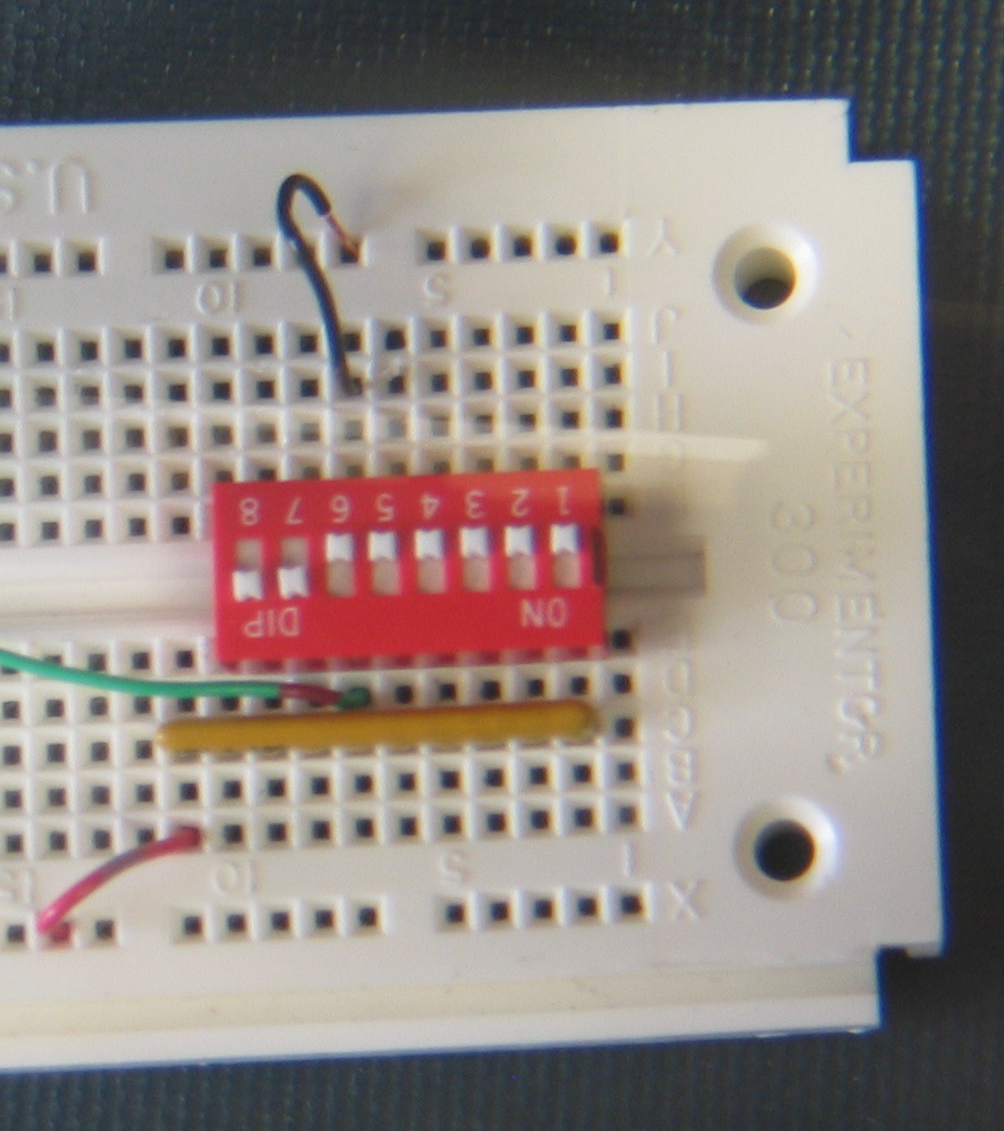
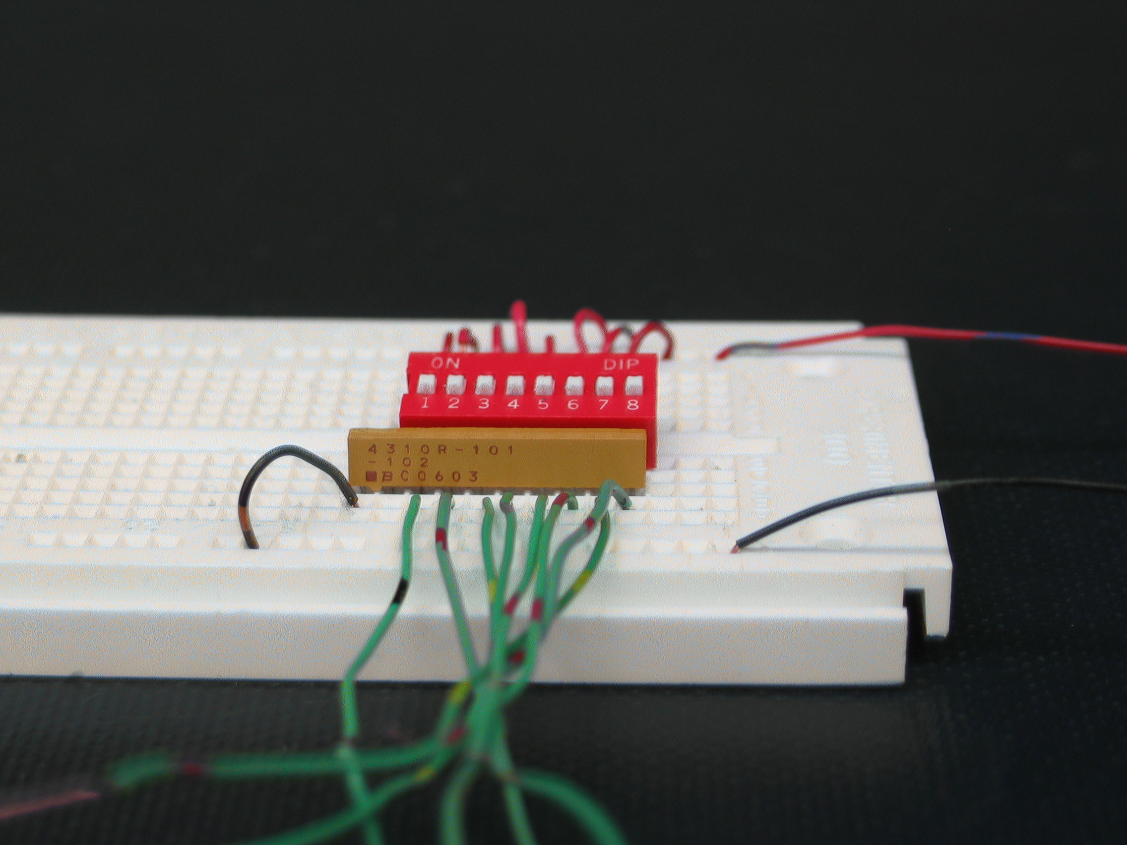
This is a side view so you can see the common pin of the
resistor array on the left.


![]()
Wilfrid Laurier University
© 2019 Wilfrid Laurier University