Simulation using Testbenches
Create a testbench to automate your simulation.
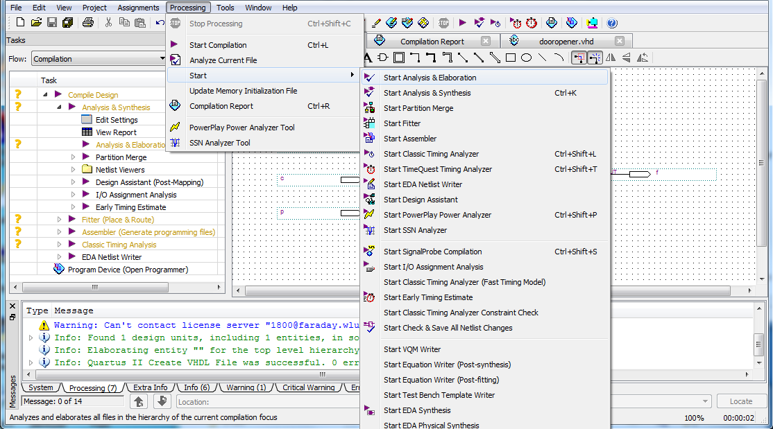
- You can get Quartus to produce a shell testbench
file by selecting
Processing | Start | Start
Test Bench Template Writer.
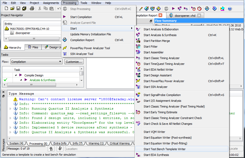
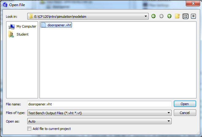
There will now be a file in your
simulation\modelsim directory.
Open it.
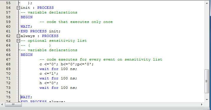
- The section near the bottom of the file is where
you put statements for your simulation.

Insert instructions for how you want the inputs to change through the
simulation.
Here's an example of the beginning for a very simple simulation:
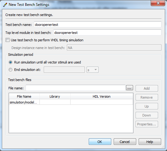
- After making the changes, you need to change the settings
to include your testbench.
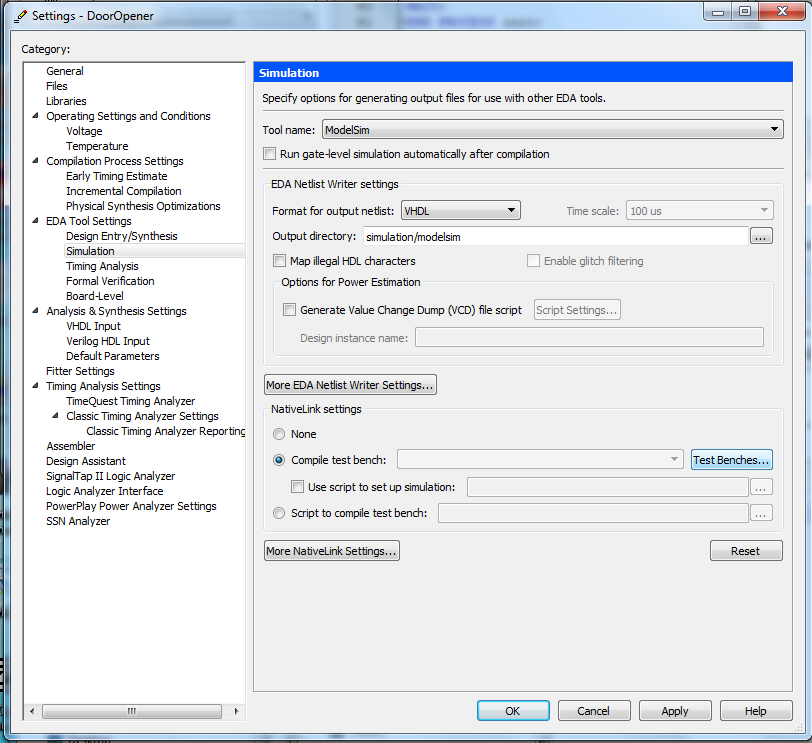
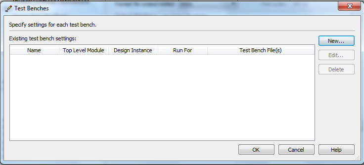
Choose a New testbench.
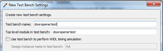
Give the test bench a name. It doesn't have to be the same as the
file name.
Now add the testbench file.
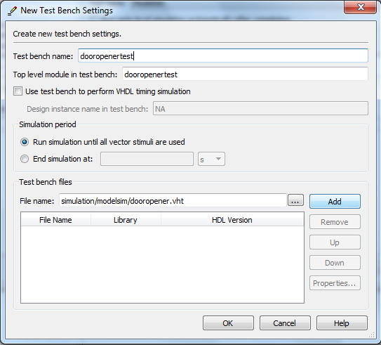
Select OK to close the New Test Bench Settings window..
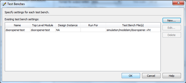
Select OK to close the Test Benches window..
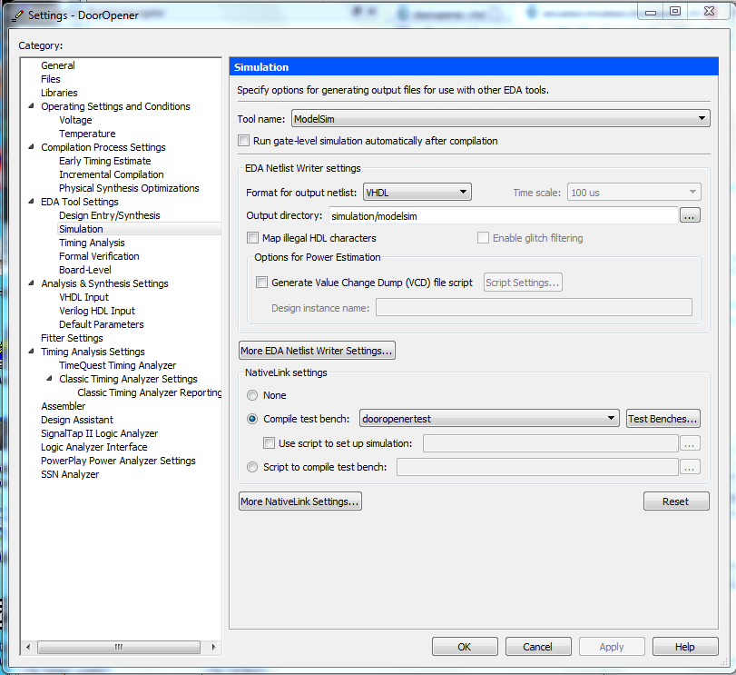
Select OK to close the Settings window..
Add the testbench VHDL file to the project and
compile for simulation.
- If it's not open, open the testbench VHDL file
using File |
Open.
Then add it to the project
using Project | Add Current File to Project.

Launch the ModelSim simulator.
- Compile the circuit for a functional simulation by
selecting
Processing | Start | Start Analysis &
Elaboration.
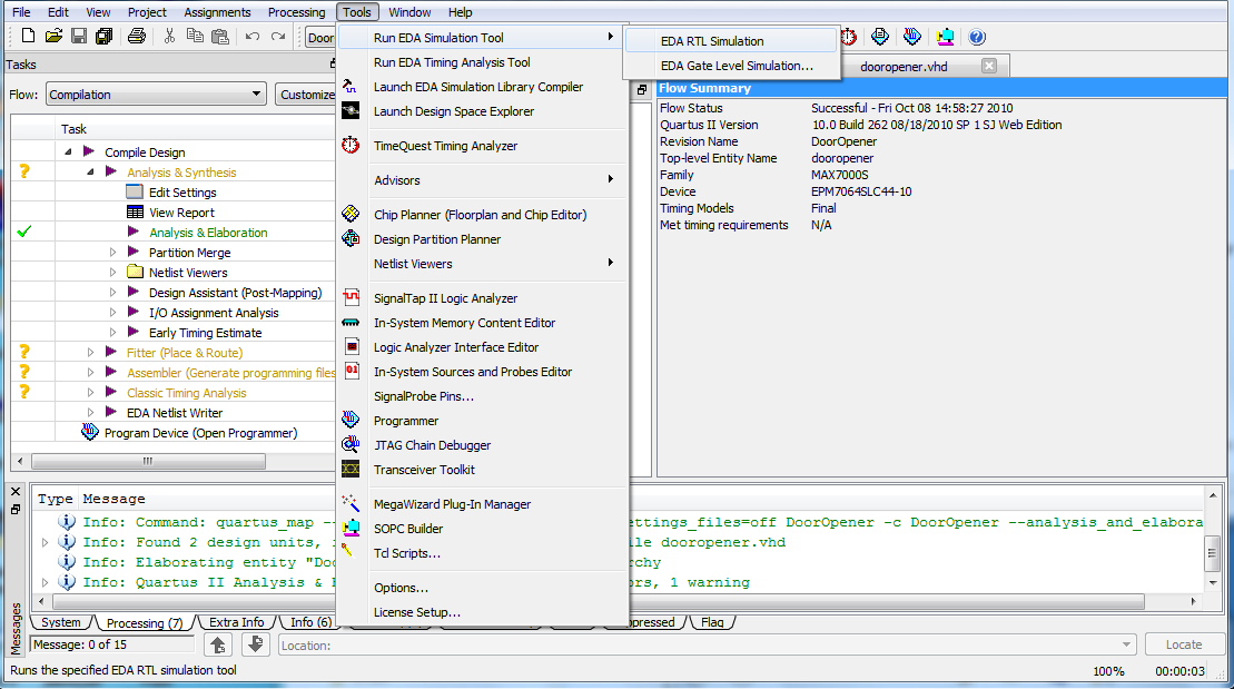
- Select Tools | Run EDA Simulation Tool |
EDA RTL Simulation.
ModelSim will display splash screen. ModelSim will
load libraries and compile the project.
The transcript pane at the bottom of the screen
indicates the scripts
that have been run (or are running).
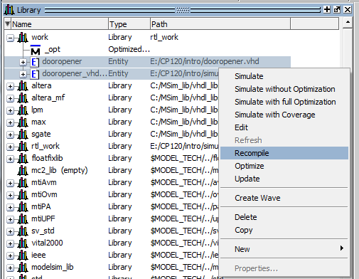
- Now your work library will
contain two VHDL files; your circuit and your
testbench. Select both,
and right click to compile both.
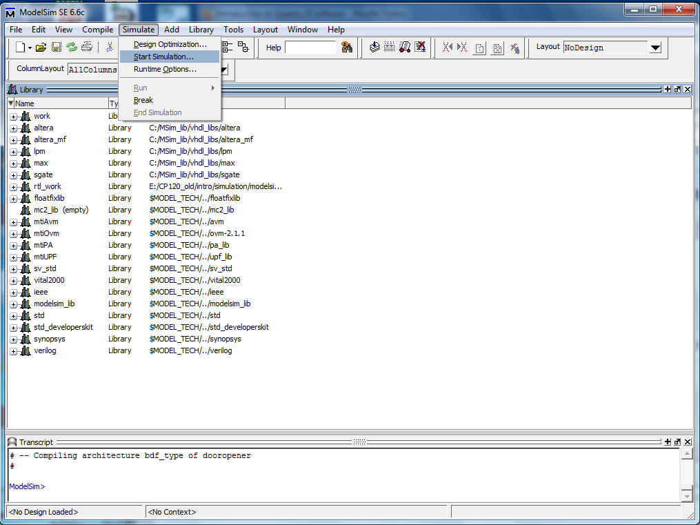
- Select Simulate | Start Simulation to put
ModelSim in simulator mode.
The Start Simulation Window opens.
- The Start Simulation window contains many tabs.
The Design tab lists the designs available for
simulation; most are system libraries.
At the top of list will be work (default name for the
library containing your program),
expand work by selecting the '+'.
All components in your design will be listed, select
the component that is the testbench.
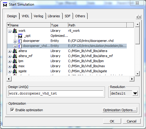
Select OK.
This will bring up other panes.
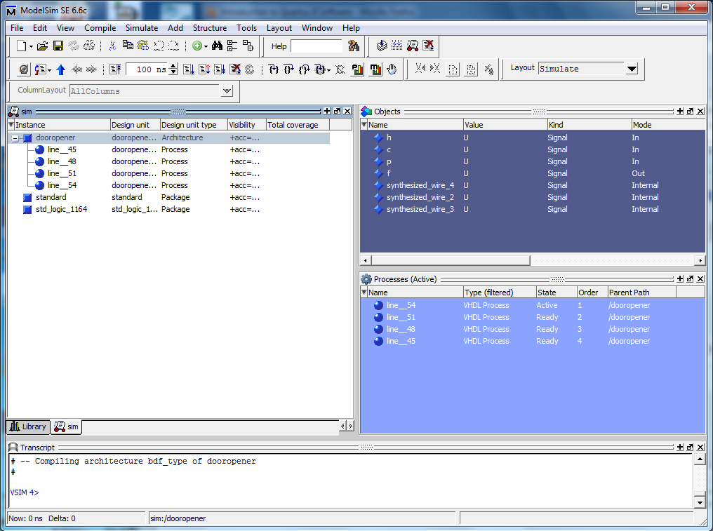
- Then the left hand side of the screen should now contain a
sim tab that displays the design units in your circuit
and the supporting libraries.
When a design unit is selected in the sim tab,
the corresponding signals are shown in the objects
window on the
right hand side of the screen.
Signals that are preceded with a plus (+) sign indicate
a bus (a group of wires with common function).
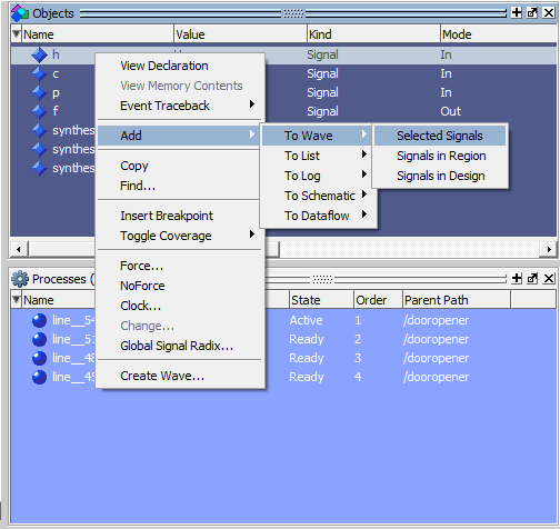
Open waveform window and add signals to be simulated.
- For each signal that you want to add to the simulation,
right click on the signal name in the Objects window
and
select Add | To Wave | Selected Signal.
Typically, you would want to add all inputs and
outputs.
A waveform window will appear in the work area.
- Alternatively, you can add a range of signals at
once by
selecting the 1st signal and then, while holding down
the shift key,
select the last signal in the range.
Then right click in the selected signal region and
select Add | To Wave | Selected Signals.
A waveform window will appear in the work area.
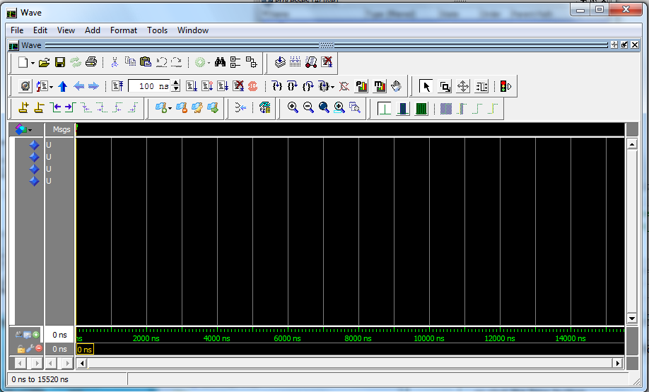
- When all signals are selected, expand the Wave
window.
- If the Wave window is not floating above the ModelSim
main screen,
use the top left icon in the wave window to undock the
window. Expand the detached window.
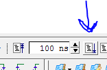
- In the tool icons, find the window that contains
the period of the signal,
e.g. 100ns. Immediately to the right of that window
will be the
run simulation icon (looks like a page with a blue
down arrow beside it).
Click on it to run the simulation.
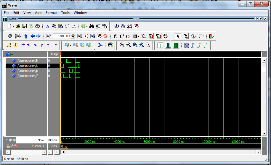
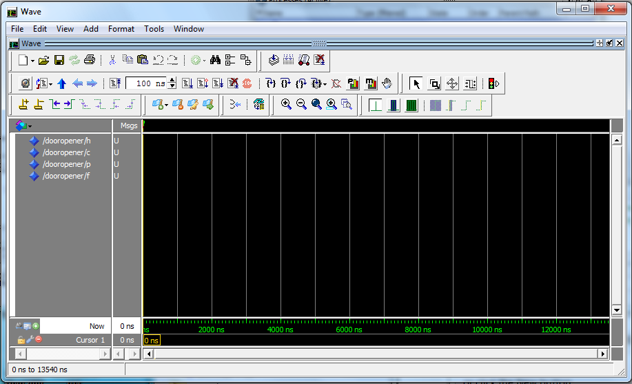
-
You should see the inputs that you entered and the
outputs from your system on the waveform.
The period of the run will correspond to the time in
the period window.
All signals should be green.
If any signals are red, then
one or more of the inputs was not specified.