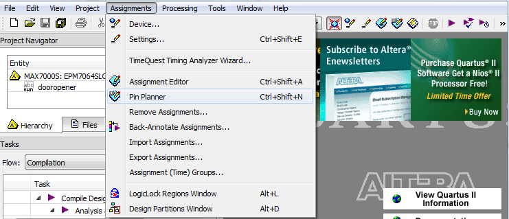
Select Assignments | Pin Planner from the pull-down menu.
You'll see a schematic of your device which shows the satus of various pins, with a list of your inputs and outputs below.
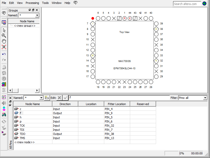
You will notice that the pins around the edges of the chip have different symbols. The plain round circles with nothing written inside of them are used for input and output.
Assign all of your pins to fit in one "bank" of CPLD connections, so only one jumper cable is required. Banks are:
For example, here is bank one.
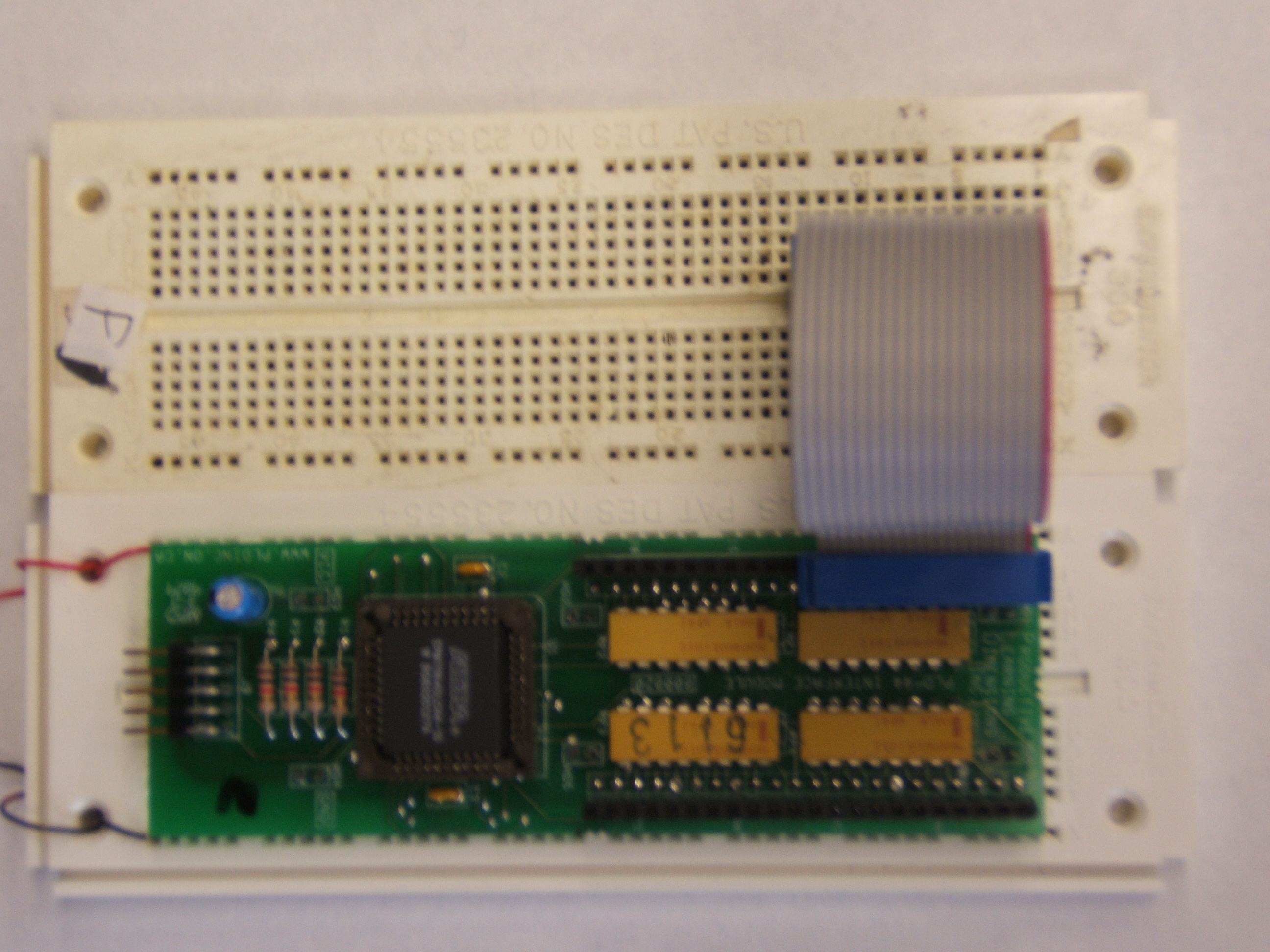
[click image to get a larger image]
Here is bank two.
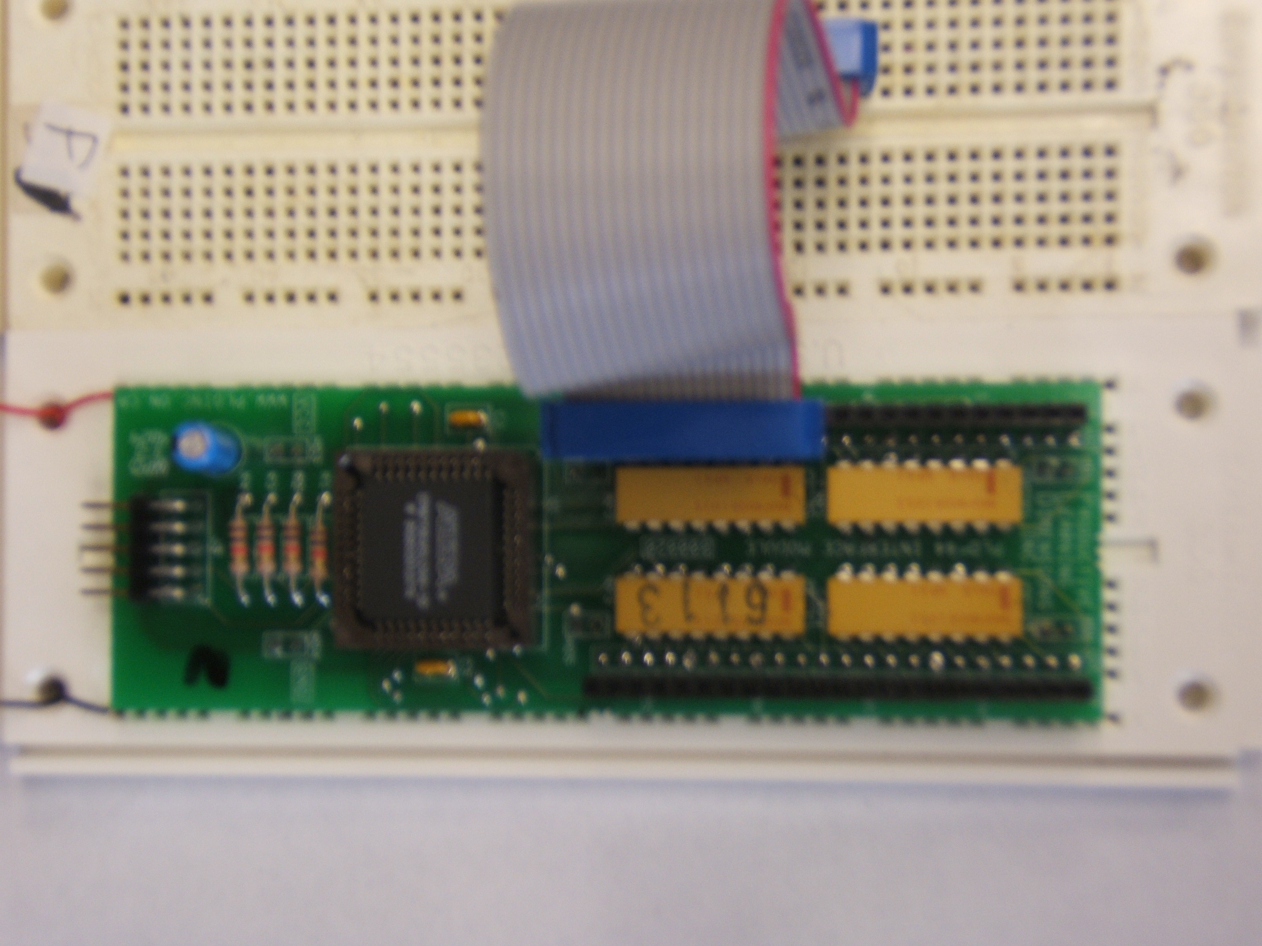
[click image to get a larger image]
Select each input and output from the bottom of the screen and
drag it on top of the pin you would like to use - make sure you click on
the name. (ie. if you want h to be pin 4, click h on the bottom of the
screen and drag it on top of the circle under the label 4).
Remember, use ONLY the plain round circles!!
You only need to assign your inputs and
outputs;
you will probably see some other signals listed that you didn't specify.
Leave them as they are.
When you are finished you can close the window.
You will need to compile your design again to fit your design on the PLD board.
Click on Processing | Start Compilation to start compilation.
Connect your USB-Blaster cable to one of the USB ports on your computer.
Note: Under linux, for the programmer to connect, do the following as
root once the programmer is plugged into the computer:
From your Quartus II binary directory, (i.e. where the quartus
executable is located), run
After this, the programmer should work.
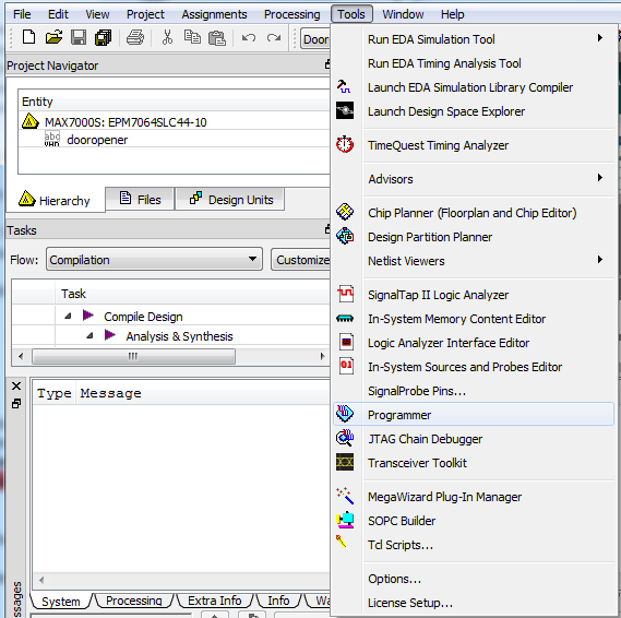
Choose Tools | Programmer. The Programmer window will open.
The selected programming hardware is identified as. If it says "USB-Blaster [USB-0] mode JTAG" you have the correct hardware (skip to the connection step).
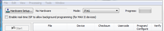
Click the Hardware Setup button to open the Hardware Setup window.
Programming hardware that is already set up appears in the Available hardware items window.
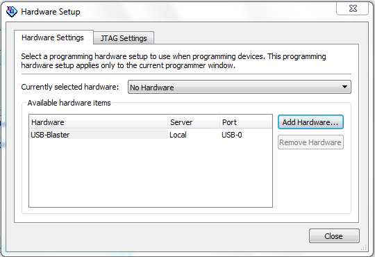
If the USB-Blaster is not listed as the Currently selected hardware, select it and click the Add Hardware.
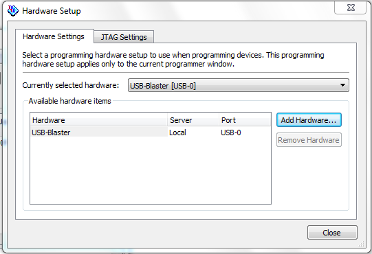
Click Close.
At the main window, ensure it displays USB-Blaster[USB-0] mode JTAG (see figure below)
Connect CPLD board to USB-Blaster cable (connected to a USB port on
your PC).
The cable should be attached so that the red edge of the USB-Blaster
cable is next to the number (usually a "1" or a "2") that has been
written on the board with a marker. IF YOU'RE NOT SURE, ASK!!!
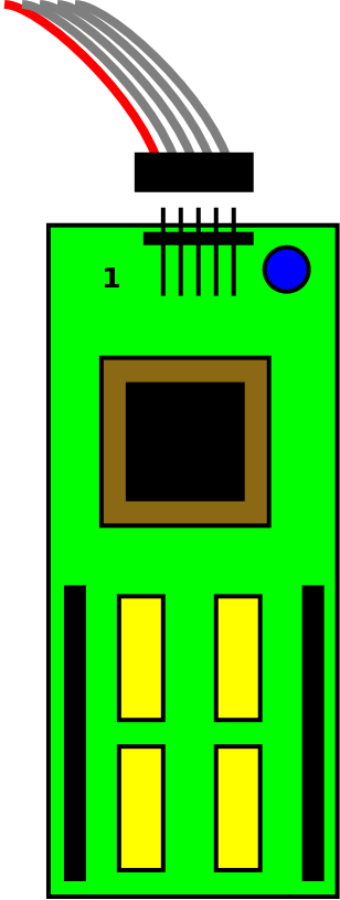
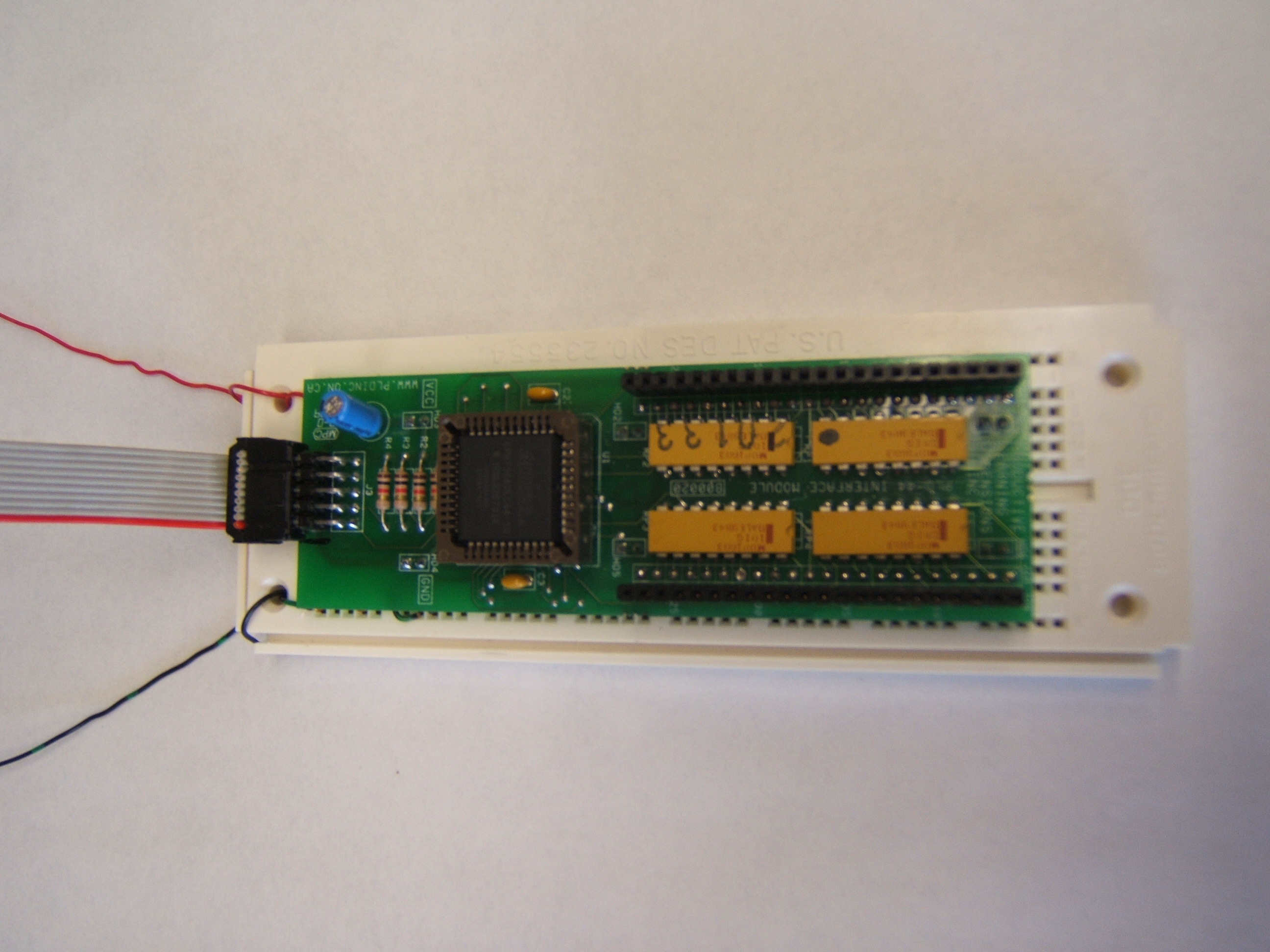
[click image to get a larger image]
Connect the ground and power (5v) to the CPLD board and turn the power on.
Click Auto Detect, your program
should detect the CPLD.
If it doesn't, there are three possibilities:
| Problem | Solution |
|---|---|
| Unable to scan device chain. | This is generally a problem with power. Check:
|
| JTAG error | This is generally a problem with the connection. Try:
|
| License error | This is generally a problem if you haven't done anything with the software recently. The server times out and loses the connection to the licencing file.
|
Once it autodetects correctly, you can proceed.
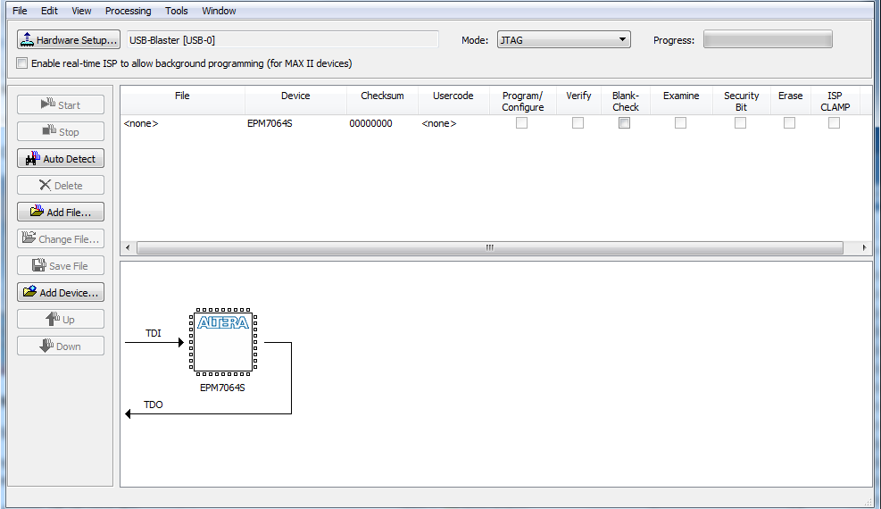
Delete the file that shows up.
Click Add File choose 'pof' file
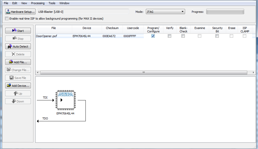
Check Program/Configure
Select Start, you should see the progress indicator increasing slowly (fast means problem).
You can unplug the USB-Blaster cable and turn off the power while you are wiring your circuit. You will not lose your program.
Use the debugger board to wire the input (use the control mode) and the output (use the display mode). (ie. c, h, p & f)
If you smell smoke turn off the power immediately and DO NOT touch the Altera chip. It gets extremely hot if it is short circuited. Check all your power and grounds, have someone else check your power and grounds - something IS wrong!! Hopefully, your chip will still work. :)