CP/PC364 Data Communications & Networks Laboratory
D/A and A/D Conversion
Overview
Digital transmission of analog data, (such as sound and video), requires analog input signals to be converted to digital signals for processing. Once received, the signals then have to be converted to back analog. These conversions are done by analog to digital (A/D) and digital to analog (D/A) converters, respectively. Although you could construct these converters from discrete components, integrated circuits specifically designed for these purposes are usually used.
Objectives
The objectives for this lab are:
- to investigate the effects of the D/A and A/D conversion process
At the beginning of the lab, you should have both an A/D circuit and a D/A circuit.
Do not dismantle the A/D and D/A circuits. Store these circuits in your lockup area for use later.
Preparation
| Great care should be taken to avoid static discharge into CMOS based chips. |
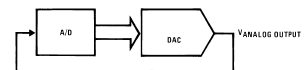
- Combine the DAC and ADC circuits by using the
ADC output lines to drive the DAC0800 as shown in the
figure below.
Warning: carefully check for the most and least significant
bits when connecting the digital lines;
the numbering of the bits is not consistent.
Drive the ADC input with a sine wave of the appropriate amplitude. Compare the analog output of the DAC with the original sine wave and sketch the signals.- How high a frequency can this system accept before the output becomes too distorted?
- What part of your system dominates this frequency limit?
A square wave input might make seeing where the output
deviates from the input easier.
Demonstrate your circuit to the lab supervisor.


