PC/CP320 Physical Computing
Output Transducers: DC Motor
Equipment
- DC motor
- variable power supply
- Zener diode
[datasheet]
Use the 1N5338BB Zener diode - oscilloscope
- multimeter
- 3.3V adapter on 5V supply
- high power resistor (10 Ω or less)
Procedure
Induced EMFs
For this part you are going to use one of the motors on the robot body and the 1N5338B Zener diode.- Connect one of the robot motors to the variable DC supply,
and attach the oscilloscope to the leads so that you can see
the voltage across the motor.

- Observe the ac component of the voltage across the motor on an oscilloscope. See how it changes as you increase power to the motor. Keep the motor voltage to less than 5V. What do you notice?
-
Look at the datasheet
for the
1N5338B Zener diode.
What is the Zener voltage for the diode?
What restriction does this put on the voltage you can apply to the motor?
If you wanted to be able to run the motor in both directions, what could you do? -
Now put the
reverse-biased
1N5338B
diode
across the motor,
(i.e. in parallel with it).
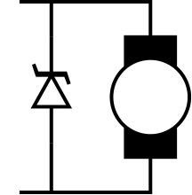
Observe the ac component of the voltage. How does it compare to the previous situation?
Sketch the voltage with and without the diode in your lab notebook.
From now on, always use a diode across the motor coils.
Demonstrate the effect of the Zener diode on noise.
Testing the motor
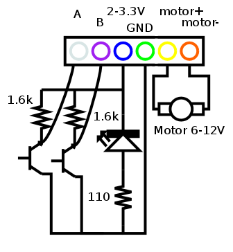
From here on you are going to use the DC motor with the built-in shaft encoder.Here is the schematic for the wiring from the DC motor:
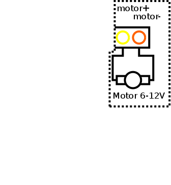
Here's the section just for the motor itself:
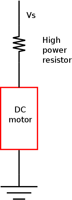
To avoid the possibility of blowing the fuse in the meter, you can determine current through a device by having it in series with a resistor. Measuring the voltage across the resistor and using Ohm's law will give the current through the device.
To measure current, place the high power resistor in series with the motor and measure the voltage across the resistor. Then use Ohm's Law to determine the current. This way you won't risk blowing the meter fuse.
- What is the motor's resistance?
Since you know the current, and you know the voltage across the motor, you can calculate the resistance using Ohm's Law.
-
Now increase the voltage slowly until the motor starts.
- What current is required to start the motor?
You can determine this as above, by determining the voltage across the series resistor. - What voltage is required to start the motor?
- Did the ratio of voltage to current match the resistance you measured? Is this what you expected?
- What current is required to start the motor?
- Normally, the current/voltage required to start the motor is
different
from the current/voltage required to keep the motor going.
Decrease the current until the motor stops.- What current is required to keep
the motor going?
You can determine this as above, by determining the voltage across the series resistor. - What voltage is required to keep the
motor going?
- Did the ratio of voltage to current match the
resistance you measured? Is this what you expected?
Demonstrate what you have determined about motor current and voltage.
- What current is required to keep
the motor going?
Testing the shaft encoder
- Now connect channels A and B of the the shaft encoder to the
oscilloscope, using the 3.3V adapter for the supply.
Here's the section just for the shaft encoder itself:
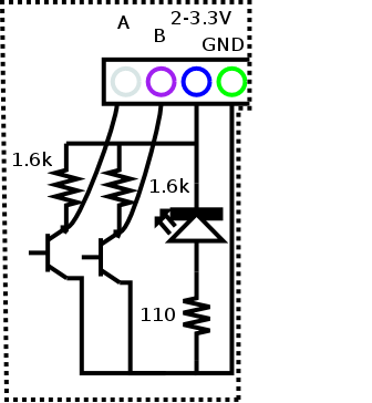
You should see an output like this when the motor is operating:
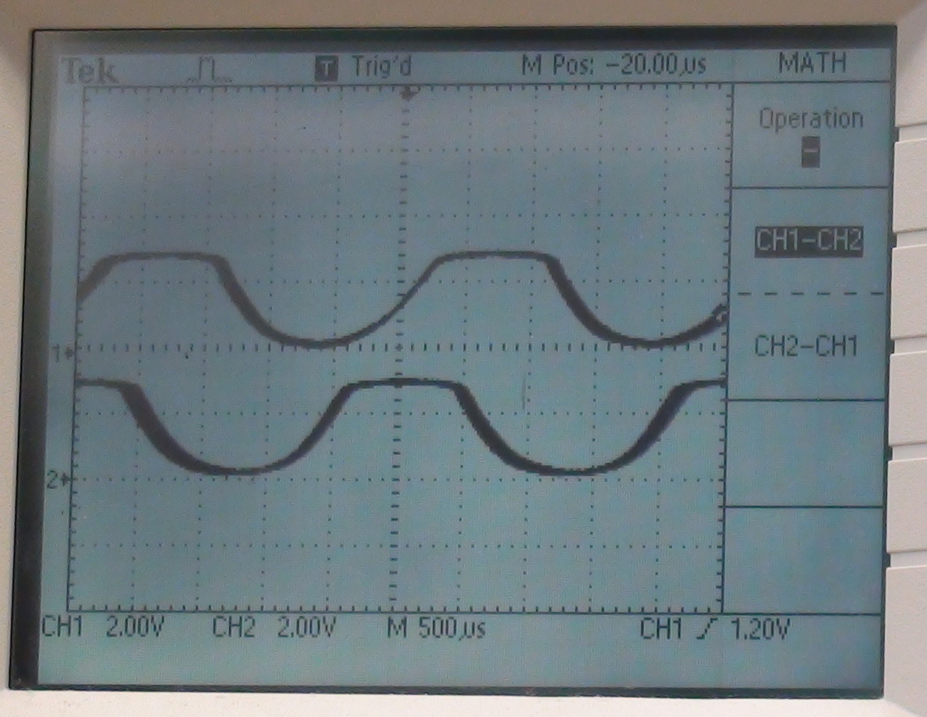
- For a range of voltages, record the voltage and the
frequency of shaft encoder pulses.
Does the speed appear to vary linearly with the motor voltage?
Sketch a graph of speed versus voltage in your lab notebook.
Demonstrate the DC motor in operation, showing how speed depends on voltage.


