PC/CP320 Physical Computing
Optoisolators Lab Requirements
Objective
Optoisolators, optocouplers, photo-isolated couplers, and photon isolators are different names for source/sensor pairs which are used to provide electrical isolation between two separate circuits. These circuits are completely separate and, typically, do not share a common power supply nor ground. An LED source is typically paired with a phototransistor, a photodiode, a light activated semiconductor relay or triac. A tungsten or neon lamp source is typically paired with a photoresistor.
- to use a commercial optoisolator
Equipment
- bench supply, function generator, oscilloscope
- Optoisolator: PS2501 -
from local server
Note: On the breadboards, in the Pi kits, there are two optoisolators, oriented in opposite directions, so that 5V signals will be one one side of the board and 3.3V signals will be on the other. Don't change this.
Procedure
Rationale
The HC-SR04 ultrasonic sensor requires one digital input signal and produces one digital output signal. However, because it is a 5V device, it cannot connect directly to Raspberry Pi GPIO pins. Using an optoisolator on each signal will solve this problem.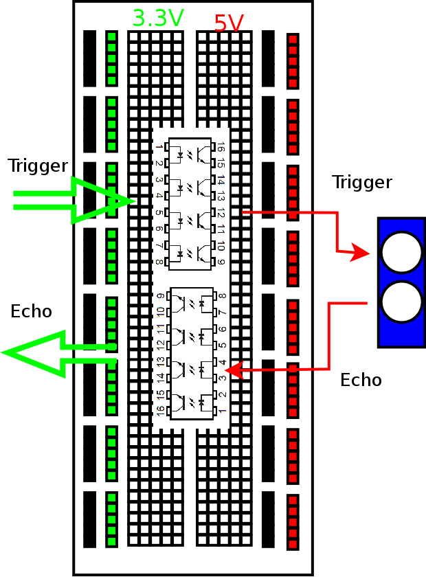
Using a commercial optoisolator
The normal connections will look like this: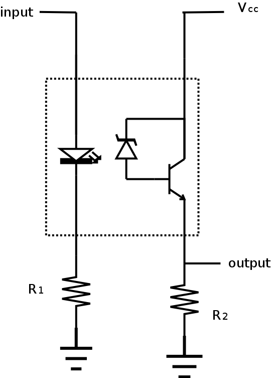
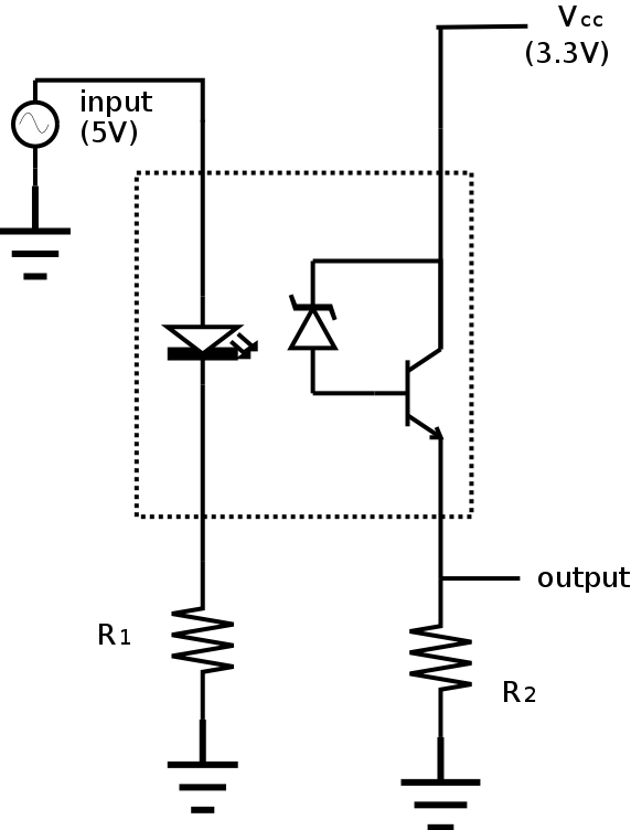
Going from 5V world to 3.3V Pi
- On the datasheet, find the recommended current
and forward voltage
for the LED. Calculate the resistance needed to produce this
current with a 5 V input and use this for the input resistor.
Find the closest available resistor and wire this up.
Use a function generator with a 0-5V square wave for your input.
-
Find the CTR (current transfer ratio) for the optoisolator.
What are the units for the CTR?
Use this and the recommended LED current to determine the
expected output current for the optoisolator.
Using a 3.3V supply and aiming for a 2.5V output determine the
resistance needed given the expected current.
Find the closest available resistor and wire this up.
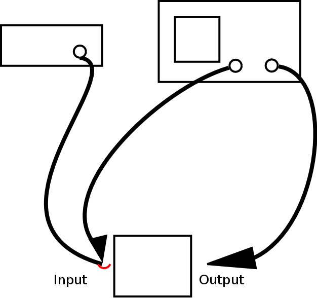
In order to show that the circuit works as expected, you'll need to display both the input and output at the same time.
If you used resistance substitution boxes, replace them with individual resistors.
Demonstrate your results to the lab supervisor.
Don't take this circuit apart; you'll be using it later with the Raspberry Pi.
Going from 3.3V Pi to 5 V world
-
Place a second optoisolator on the
breadboard
in the opposite direction from the other one, so that one side of
the breadboard is exclusively for 5V levels and the other closest
to the Pi is exclusively for 3.3V levels.
- On the datasheet, find the recommended current
and forward voltage
for the LED. Calculate the resistance needed to produce this
current with a 3.3 V input and use this for the input resistor.
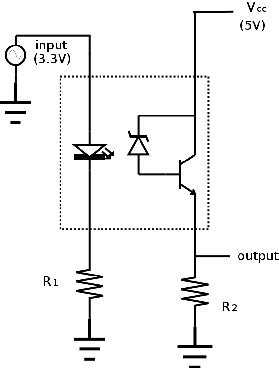
Find the closest available resistor and wire this up.
Use a function generator with a 0-3.3V square wave for your input.
-
Find the CTR (current transfer ratio) for the optoisolator.
What are the units for the CTR?
Use this and the recommended LED current to determine the
expected output current for the optoisolator.
Using a 5V supply and aiming for a 4V output determine the
resistance needed given the expected current.
Find the closest available resistor and wire this up.
In order to show that the circuit works as expected, you'll need to display both the input and output at the same time.
If you used resistance substitution boxes, replace them with individual resistors.
Demonstrate your results to the lab supervisor.
Don't take this circuit apart; you'll be using it later with the Raspberry Pi.


