PC/CP320 Physical Computing
Introduction to Operational Amplifiers
Objectives
An operational amplifier or op-amp is a high gain DC
amplifier; the operational portion of the name
derives
from its original application for performing mathematical
operations
in analog computers. The op-amp is an analog device that is very
widely used in both analog and digital design because its
operating
characteristics can be significantly changed by connecting
different
external components.
The objectives for this lab are:
- to investigate the behaviour of an op-amp in an open-loop
configuration - the comparator
- operation of inverting and non-inverting inputs
- impact of op-amp gain
- limitations imposed by supply voltages
- to investigate the behaviour of an op-amp in one of the many
closed-loop configurations - the inverting amplifier
- how to adjust gain
- limitations imposed by supply voltages
Equipment
- textbook
- bench supply, oscilloscope, function generator
- breadboard, variable resistor, resistors
- for open-loop circuit and inverting amplifier use the LM741:
data sheet from local server.
Procedure
The comparator - the op-amp in an open-loop
configuration
- Operational amplifiers are differential amplifiers that
amplify the difference in voltage between the two
input connections or Vo =
Av (V+ - V- )
where Av is the voltage gain.
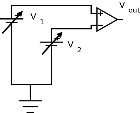
Using the LM741, construct the
open-loop comparator circuit shown.
Since you will be having negative supply voltages that are not the same
as ground, use white wires for the negative supply voltage. There are
white alligator clips to help with this.
Use ±12V bench (i.e. fixed) supplies for the
supply voltages (note the above caution about polarity).
(Note that the diagram does not explicitly show the supply
voltages for the op amp.)
Don't confuse the positive supply and the non-inverting input, or
the negative supply and the inverting input. Always ensure you know
which one you are talking about.

Precautions should be taken to
insure that the
power
supply to the operational amplifier never becomes
reversed in
polarity. The input voltage at the positive supply
pin must be greater than the input voltage at the
negative
supply pin. If polarity is reversed to the IC, the
internal conductors can fuse and destroy the
chip.
Use the two variable dc supplies for V1 and
V2 (from the supply on top of the bench).
Never apply inputs before
establishing supply voltages.
Don't confuse the positive supply and the non-inverting input, or
the negative supply and the inverting input. Always ensure you know
which one you are talking about.
Monitor Vout with a digital voltmeter.
Sketch the circuit in your lab notebook. Since
you will be doing a lot of circuit variations, it is
important to get into the habit of always sketching
the circuit in your lab notebook. Always include the
supply voltages.
- Set V1 to 1 volt, and V2
equal to 0 volts. Note Vout.
- Increase V2 slowly to 2 volts, while watching
Vout. Don't change V1.
If you notice anything happen to Vout,
record what happens and the value of V2.
- Now leave V2 at two volts, and
increase V1 slowly to 3 volts, while
watching
Vout.
If you notice anything happen to Vout,
record what happens and the value of V1.
- Repeat the pattern of the last two steps, leapfrogging
V1 and V2 until
they reach the positive
supply voltage or until you see a pattern emerge.
What pattern did you observe in Vout?
- Since Vo = Av (V+ - V_ ),
what output would
you expect if you had unity voltage gain, i.e. Av =
1? Explain.
Knowing this, what can you say about Av for this
op-amp, e.g. is
it much less than 1, is it less than 1, equal to 1,
greater than 1, much greater than 1?
Explain your reasoning.
Demonstrate your results (i.e. explain why this is called a
"comparator") to the lab supervisor.
The inverting amplifier - one of the many
closed-loop configurations
An inverting amplifier circuit produces
an
amplified output signal that is 180° out of phase with
the input signal.
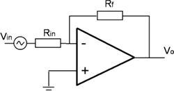
Using an LM741, construct the closed-loop inverting
amplifier
circuit shown to the left. Use ±12V for the supply
voltages. Use a feedback
resistor, Rf, of 10 kOhms and an
input resistor, Rin,
of 1 kOhms. When you
sketch the circuit in your lab notebook, note the feedback
and input resistor values.
In order to show that the circuit works as
expected, you'll need to display both the input and output at the same
time.
Drive the amplifier with a 1 kHz sine wave with a DC offset of
zero. Start with a small amplitude and increase
the amplitude; note the signal behaviour as the amplitude
increases. Sketch input and output; include measurements
of amplitude.
At what point does the signal saturate (output signal will no
longer look like a sine wave)? For the remainder of this
exercise, use a reasonable amplitude (not too small but do
not saturate the output).
- Theoretically, Vo = Av
(V+ - V_ )
where Av
is the open-loop voltage gain. The
closed-loop gain
is a
function of the feedback resistor and the input resistor.
For the circuit in the previous question
(nonsaturated state), what
closed-loop gain did you observe? How does
this relate to the resistors used in the circuit?
- What maximum output swing did you observe? What is this as a
function of the rails?
- Since you know the equation (question 2) and you know the
supply voltages you used, you can calculate the
point at which saturation would occur,
i.e. for what value of Vin? Show the
calculation.
- Measure the voltage at the inverting input. Sketch the
circuit and indicate how you are doing this measure.
The inverting input is said to be at virtual ground. A
virtual ground is a voltage ground because the
point is at 0V; however, it is not a current ground because
it cannot sink any current.
- Change the supply voltage to +5V/-12V. Sketch your circuit
and show both the input and output voltages. Do you
understand why the supply voltages are called the rails?
Note the relationship of Vo to the supply voltages; does
Vo reach the rails?
-
Change the supply voltage to +5V/0V.
(What is this
configuration called?) Sketch your circuit
and show both the input and output voltages. Is this
consistent with what happened in the previous item?
What does this illustrate about using inverting
amplifiers in single supply configurations?
- Return to a supply voltage of ±12V. Try sine waves of
different frequencies; at some point the amplifier will
stop working properly. Note what happens and when it
happens.
- What happens if you try different resistor values? Hold
either the feedback or input resistor constant and change
the other resistor. What is
the relationship between the resistors and the gain?
Do you see the voltage divider
formed by Rin and Rf?
Demonstrate the inverting amplifier circuit to the lab
supervisor. Be prepared to explain the
circuit's
behaviour.
In order to show that the circuit works as
expected, you'll need to display both the input and output at the same
time.
You do not have to keep the circuit past the
demonstration.
Have the lab supervisor sign your lab
notebook before you leave the lab.
Wilfrid Laurier University
© 2019 Wilfrid Laurier University


