PC/CP320 Physical Computing
Power MOSFET (N channel)
Equipment
- IRF510 -- Fairchild, International Rectifier
| Great care should be taken to avoid static discharge into the chips used in this lab and should always be taken when using CMOS based chips. |
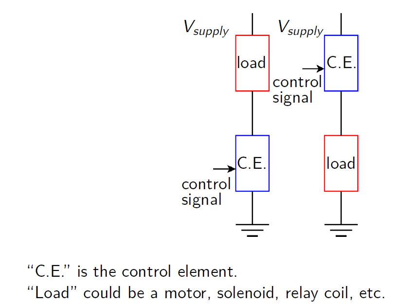
- Using a
high current resistor
of between 50 and 150 Ω
for your
load, wire up the circuit on the left of the drawing above with
the MOSFET as your control element.
Use a 12V supply.
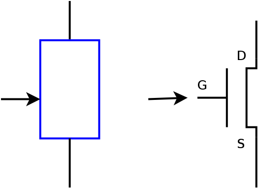
Remember that when using a MOSFET, you do not need a gate resistor.
- Using the variable voltage supply for the input to the gate,
see what input voltages are required to produce a
voltage across the load of 1V, 2V, 3V, 4V, and 5V.
- Plot a graph of Vload vs.
Vinput.
- Now switch the positions of the load and the MOSFET, as in the
right hand picture above.
- Repeat the investigation of input voltage required to produce
each of the desired load voltages.
- Plot the results on the same graph, and summarize how the
relative positions of the load and control element affect the
input voltage required.
Demonstrate the relationships between Vload and Vinput for the two configurations.


