PC/CP320 Physical Computing
Controlling Power to a DC Motor Using an H-bridge
Objective
We have various output transducers whose power can be controlled using various techniques. The pairing of an output transducer and a control circuit is not limited to the ones you will be investigating; although some pairings make more sense than others. The specific objectives for this year are:
- to control the operation of a DC motor using an H-bridge
- to control the speed of a DC motor over a range of input signal values
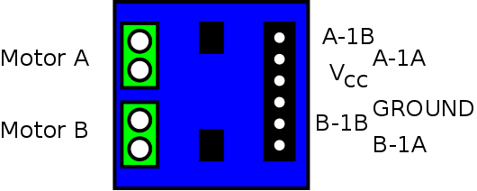
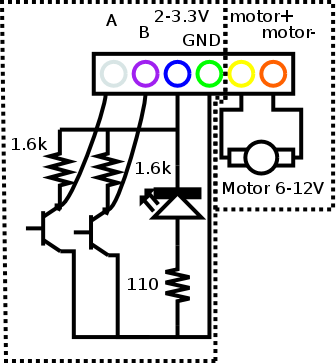
The breakout board has 2 H-bridges on it, labeled "A" and "B", so that one board can control two motors. The only things they have in common is the supply voltage and ground.
L9110 H-Bridge datasheet
The shaft encoder connections are electrically separate from the motor connections.
These are the shaft encoder connections.
Note the wire colours to identify each of the connections.
Equipment
- DC Motor
- H-bridge
Procedure
Investigating the datasheet
Open the datasheet for the H-bridge and answer the following questions:- Will external diodes need to be used across the motor, or are they included inside the H-bridge?
- What are the limits for the motor supply voltage? Will the fixed bench supplies be OK?
- What are the limits for the control signal voltage? Will the Raspberry Pi GPIO pins be OK?
- Are there any signals going back to the Pi? Will optoisolators be needed?
-
Explain your findings to the lab
supervisor.
DC motor direction
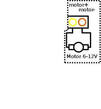
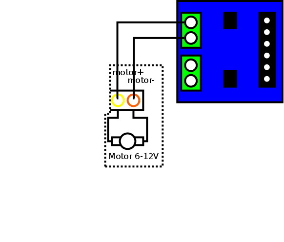
- Connect the two motor power pins to the screw terminals
for one motor on the H-bridge. Use the 5V bench supply for
power.
- Apply a positive signal to one input and ground to the other and note the direction the motor rotates.
- Now reverse the previous situation; apply ground to the
first input and a positive signal to the other
and note the directions the motor rotates.
Does the behaviour match the data sheet?
Demonstrate and explain your findings to the lab supervisor.
Speed control with PWM
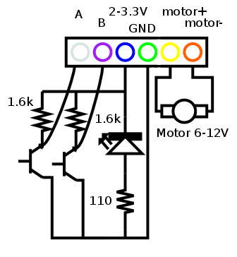
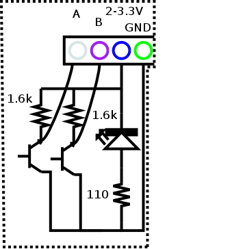
- Create a 0-3.3V 1kHz square wave with the function generator and connect it to one of the control inputs of the H-bridge. Connect the other input to ground.
- Adjust the duty cycle of the signal and see how the motor
speed changes.
What is the smallest duty cycle which will keep the motor running? - Now take the input which was tied to ground and tie it to
3.3V instead.
Adjust the duty cycle of the signal and see how the motor speed changes.
Did it operate as expected? -
Demonstrate and explain your findings to the lab
supervisor.


