PC/CP320 Physical Computing
Controlling Power (DC Motor)
Objective
We have various output transducers whose power can be controlled using various techniques. The pairing of an output transducer and a control circuit is not limited to the ones you will be investigating; although some pairings make more sense than others. The specific objectives for this year are:
- to control the operation of a DC motor using an IRLZ44N power MOSFET
- to control the speed of a DC motor over a range of input signal values
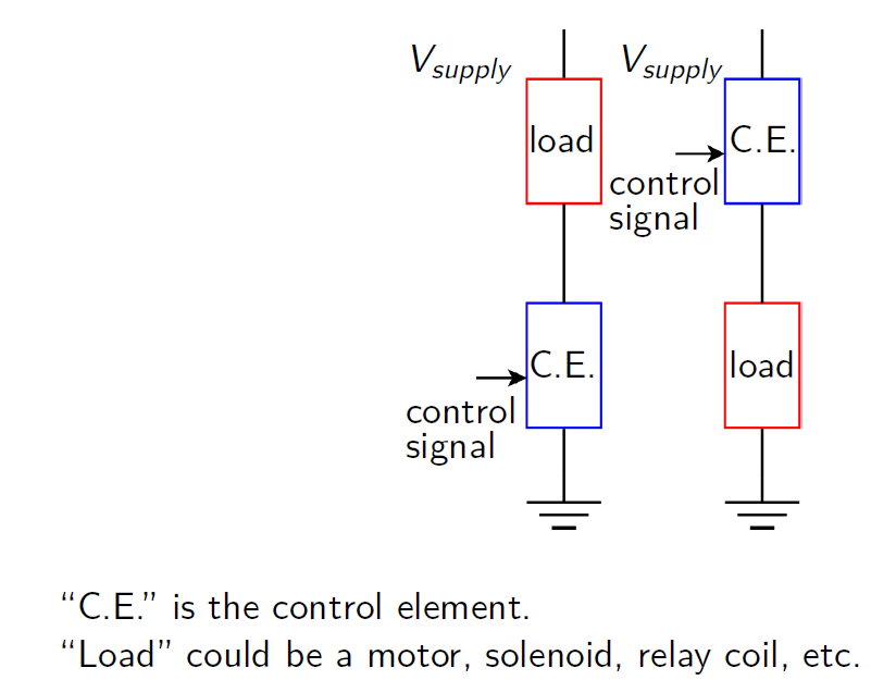
Remember that you need to put diodes across the coils of inductive devices to avoid back EMFs. (Think about which way the diode needs to go.)
Equipment
- DC Motor
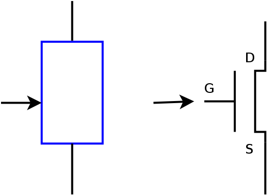
- Power MOSFET
- IRLZ44N -- International Rectifier
- Zener diode
[datasheet]
Use the 1N5925B Zener diode - LM324 op amp data sheet (from local server)
Procedure
-
DC motor investigation
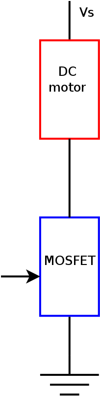
Here is the schematic for the wiring from the DC motor:
Here's the section just for the motor itself:
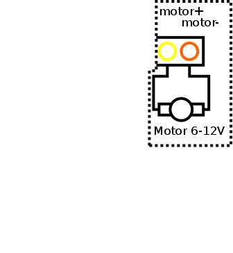
Put a Zener diode across the motor to avoid induced EMFs.
Based on the orientation of the diode, think of which direction voltage can be applied to the motor in order for it to run.
Test this by using the variable supply and using it to run the motor. Don't let the motor voltage get bigger than about 9V. Why?
Now reverse the diode, and test the motor with voltage applied in the opposite direction. Don't let the motor voltage get bigger than about 9V.
Demonstrate and explain your findings to the lab supervisor.
-
Driving a DC motor using an op amp
Wire up an op amp as a buffer using one of the variable supplies set to 9V as the supply votage.
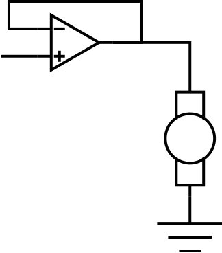
Feed the voltage from the other variable supply into the buffer and use the output of the op amp to try and run the motor. Does it work?
If it doesn't work, observe the voltages at the input and output of the buffer. How should they be related? Is that what actually happens?
What is the limitation of the op amp that might prevent it from running the motor directly?
Demonstrate and explain your findings to the lab supervisor.
-
Power MOSFET control investigation
Wire up the MOSFET and motor with one of the variable supplies set to 9V in the following configuration:
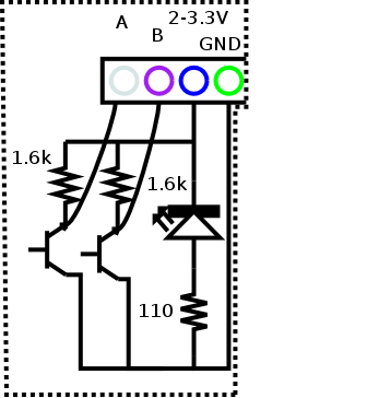
Use the 3.3V adapter on the 5V supply to provide power for the shaft encoder electronics, and connect both outputs to the oscilloscope.
Here's the section just for the shaft encoder:
Using the other variable supply for the gate of the MOSFET, start at zero and increase the voltage until the motor starts. Record the voltage required.
Is there a gate voltage at beyond which the motor speed doesn't change? If so, record it.
Sketch a graph of frequency versus gate voltage. Is it linear?
Why not just use the fixed 12V supply instead of the variable supply set to 9V?
Demonstrate and explain your findings to the lab supervisor.
-
Driving a DC motor using an op amp and MOSFET
Now instead of using the op amp to run the motor directly, feed it into the gate of the MOSFET in the configuration from above to run the DC motor.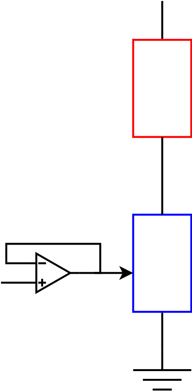
How does this new circuit get around the op amp limitation you mentioned earlier?
Demonstrate and explain your findings to the lab supervisor.


