    VGA Graphics Card Overview

    This outlines the following sections of the project:
|
 |
Project Objective
Design and construct a simple VGA graphics card capable of displaying an image stored in RAM.
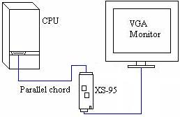
To develop an understanding of how the XS95 board simulates a simple graphics card, the test code given by the manufacturers manual was used as a starting point. This code was an implementation of a VGA generator that displays the image stored in the board's RAM onto a VGA monitor.
The sample code first had to go through a four-stage software process of, design entry, synthesis, implementation and programming, where at completion an SVF file is created. This file was loaded into the GSXload utility and then from the CPU to the CPLD through a bit-stream.
After disconnection of the parallel port a visual output of the test program was evident on the VGA monitor.
VGA Card Components
XESS-95 board
 VHDL Sample Code

   - link to XESS sample code.
- VGA Monitor
- Parallel port cable
 XILINX Software & Utilities:

   - Project Manager: Executes the four processes described in
                      the objective.

   - GXSLOAD:         Takes SVF files and loads it into the CPLD.
                      Also, stores HEX files into the board's RAM.

   - GXSSETCLK:       Using a divisor changes the 100 KHz clock
                      on the board to a desired frequency.
                      (i.e. 25KHz)

   - GXSPORT:        Sends input data to the board (not used).

   - GXSTEST:        Checks to see if the board is functioning
                     properly.
|
|
Designs
(i) Laurier Logo: Sample code: logo.vhd
The function of the VHD program is to load the data stored in the RAM and display it on the VGA monitor.
For the program to work properly the file stored in RAM must be exactly 128 pixels in length. Each pixel is repesented by
8 bits, each having the possibility of being 1 of 64 colours. This particular program makes use of 11 of those colours.
Since each pixel is represented by 8 bits an image half the width of the screen can be displayed.
(ii) Wide Screen: Sample code: wide.vhd
This program is a modified version of logo.vhd that makes use of the full width of the screen.
For this to be accomplished, each pixel must be represented by 4 bits. Each address holds 8 bits therfore
2 pixels are stored in each address location. To seperate the two 4 bit pixels we addressed the RAM every other clock
cycle and on the remaining clock cycles the 4 least significant bits were shifted out and replaced by the 4 most significant.
The board has the ability to produce 2^6 = 64 colours, but since there are only 2^4 distinct pixel combinations only 16 colours can be used.
(iii) Colour: Sample code: colours.vhd
This program displays all the possible colour combinations the XESS board can produce.
As mentioned above, there are 6 input pins on the chip allowing 64 colours. This program, producing a colour
spectrum on the monitor, was used as a reference for the logo program to determine what colours would be used.
Hex Files
HEX files were used to code a image into the RAM. This coding is based on the hexidecimal system
where 0-F represents the numbers 0 to 15. Each line in the text based hex file begins with a number in hex representing
the number of pixels in each row followed by the starting address of the first pixel in the row.
eg. -080010FF77FGA0FFFFFFFF
- The numbers "08" in hex equals 8 in decimal. Therefore there are 8 pixels represented by 16 four bit numbers (i.e. F=1111).
"0010" tells us the first pixel of this particular row is located in the 16th address (10 in hex = 16 in decimal).
- The body of each line starts after the addressing header and can consist of any hexidecimal number. The colour of
each pixel is determined by the program itself in a list of cases.
- In the logo.vhd and colours.vhd programs, using the example above, the first two F's would be seen as the first pixel,
the two 7's as the second and so on. The wide.vhd program would see the first F as the first pixel, the next
F as the second pixel, the 7 as the third pixel and so on.
- The advantages of the first first case is the ability to use up to 64 colours, however only making use of half the width of the screen.
The advantages of the second case is the ability to use the entire width of the screen, however only use a possible 16 colours.
    (i) Laurier Logo:  Sample code:  logo.hex
                       Logo GIF:  laurier.gif
(ii) Wide Screen: Sample code: wide.hex
(iii) Colour: Sample code: colour.hex
** The actual images for the laurier logo and colour spectrum that were displayed on the monitor are shown below in screenshots.
Screenshots
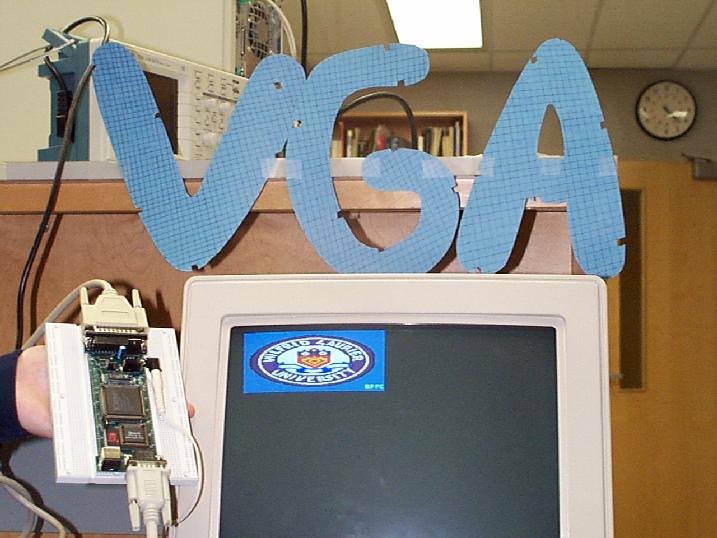 |
Logo.vhd program using the logo.hex file |
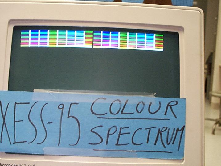 |
Colours.vhd program using the colour.hex file |
Back to top