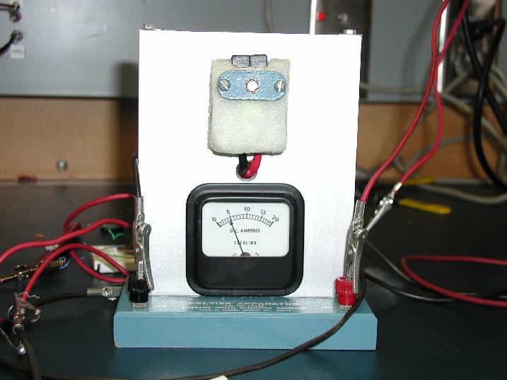
Here are several pictures of our finished prototype. The first picture is of the Peltier Apparatus itself. As you can see, when the apparatus is activated through the transistor relay it is getting a current of around 5 A. This is less than we would have liked, but still enough to get the results we are looking for.
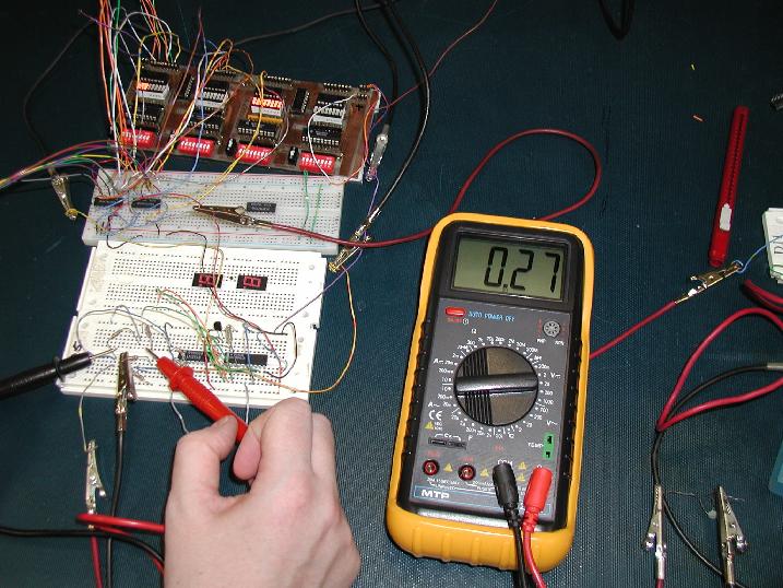
This picture is of the main circuit. The top breadboard contains our comparator circuit, which in this picture is activated. Notice on the debuggerboard how the first set of inputs has several inputs active and that the second has none of the inputs active. This corresponds to the 'On' scenario in our circuit, as should be expected, the device is active. When this picture was taken, the thermistor was at room temperature, and the voltage from our bridge circuit is about 0.27 mV (as can be seen on the multimeter display).
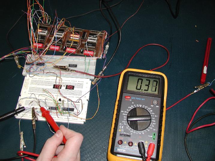
This final picture corresponds to when the thermistor is being cooled by the Peltier Apparatus. At this stage it is at about half way to it's coldest possible setting, and the voltage is noticibly higher than before, about 0.37 mV (at maximum coldness, the voltage is around 0.5 mV).