Priority Control
for Traffic
Light System 
By: Amol Shah
Circuit Description:
The Opticom Control for a traffic light system is a system
that simulates a traffic light controller for an intersection. The situations that are taken into account
are priority control for emergency vehicles and routine traffic at
intersections.
The system originally starts at a random state where the
lights are green in either the North/South direction or red in the east/west
direction or vice versa. When a car
approaches the intersection, which has a red signal, a button on the keypad is
pressed to signal that a car has arrived.
The system will then change the lights at the intersection to suit the
car, which approached first. The system
is run through the PLD, which is programmed to take every case into
consideration.
As normal traffic is flowing, the need for a priority
control for emergency vehicles is needed.
With the use of a photo-resistor (light sensitive sensor), emergency
vehicles are sensed and the lights are instantly changed to whatever direction
the emergency vehicle is approaching.
Design Specification:
Inputs:
Clk – used to calculate the amount of time it takes for
the each light to change colour.
Init – Puts the system in an initial state of normal
traffic flow.
carNS – notifies system of a car in the direction of
North/South
carEW - notifies system of a car in the direction of
East/West
emerNS - notifies system of an emergency vehicle
approaching in the direction of North/South
emerEW - notifies system of an emergency vehicle
approaching in the direction of East/West
Outputs:
YlightEW – puts yellow light in the east/west direction
GlightEW - puts green light in the east/west direction
RlightEW - puts red light in the east/west direction
YlightNS - puts yellow light in the North/south direction
GlightNS - puts Green light in the North/south direction
RlightNS - puts Red light in the North/south direction
Block Diagram:
Photoresistor P L D
![]()
![]()
![]()
![]()
![]()
![]()
![]()
Logic Device Description:
State
Diagram:
#1) going East/West:
CarNS or emerg NS

CarEW or emer EW
Emer EW
|
CarNS or emerg NS |
|
CarEW or emer EW |
|
Emer EW |
#2)
going North/South:
CarEW or emerg EW

CarNE or emer NS
Emer NS
|
CarEW or emerg EW |
|
CarNE or emer NS |
|
Emer NS |
VHDL Code
LIBRARY
IEEE;
USE
IEEE.std_logic_1164.all;
use
IEEE.std_logic_unsigned.all;
entity
traffic is
port (clk, carNS, carEW, emergEW, emergNS :
in std_logic;
rlightEW, ylightEW, glightEW,
rlightNS, ylightNS, glightNS :
out std_logic);
end
traffic;
ARCHITECTURE
inner of traffic is
type
state_type is (Red, Yellow, Green);
signal
EW, NS : state_type;
signal
c1, c2 : std_logic_vector (3 downto 0);
begin
process(clk)
begin
if clk = '1' and clk'EVENT then
case EW is
when Red
=>
if
emergEW = '1' then
NS
<= Yellow;
c1
<= "0000";
elsif
NS = Red then
EW
<= Green;
elsif
carEW = '1' then
c1
<= c1 + '1';
if
c1 = "1110" then
NS
<= Yellow;
c1 <= "0000";
end
if;
end
if;
when Yellow
=>
c1
<= c1 + '1';
if
c1 = "1010" then
EW
<= Red;
NS
<= Green;
c1
<= "0000";
end
if;
when Green
=>
end case;
case NS is
when Red
=>
if
emergNS = '1' then
EW
<= Yellow;
c2
<= "0000";
elsif
carNS = '1' then
c2
<= c2 + '1';
if
c2 = "1110" then
EW
<= Yellow;
c2
<= "0000";
end
if;
end
if;
when Yellow
=>
c2
<= c2 + '1';
if
c2 = "1010" then
NS
<= Red;
EW
<= Green;
c2
<= "0000";
end
if;
when Green
=>
end case;
if EW = Red then
rlightEW
<= '1'; ylightEW <= '0'; glightEW <= '0';
elsif EW = Green then
rlightEW
<= '0'; ylightEW <= '0'; glightEW <= '1';
elsif EW = Yellow then
rlightEW
<= '0'; ylightEW <= '1'; glightEW <= '0';
end if;
if NS = Red then
rlightNS
<= '1'; ylightNS <= '0'; glightNS <= '0';
elsif NS = Green then
rlightNS
<= '0'; ylightNS <= '0'; glightNS <= '1';
elsif NS = Yellow then
rlightNS
<= '0'; ylightNS <= '1'; glightNS <= '0';
end if;
end if;
end process;
end
inner;
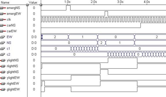
Timing Diagram:
Pin-out Diagram for PLD:
R R
e E E
m S
S
c e c
E E
a r a
R R
r g r V G
G G c G V V
N E E C N
N N l N E E
S W W C D
D D k D D D
-----------------------------------_
/ 6 5 4 3
2 1 44 43 42 41 40 |
#TDI
| 7 39 | RESERVED
emergNS
| 8 38 | #TDO
ylightEW |
9 37 | RESERVED
GND |
10 36 |
RESERVED
rlightNS | 11 35 | VCC
rlightEW | 12 EPM7032SLC44-5
34 | RESERVED
#TMS |
13 33 |
RESERVED
RESERVED | 14 32 | #TCK
VCC |
15 31 |
RESERVED
glightNS | 16 30 | GND
ylightNS | 17 29 | RESERVED
|_ 18 19 20 21 22 23 24 25 26 27
28 _|
------------------------------------
g R R R G
V R R R R R
l E E E N
C E E E E E
i S S S D
C S S S S S
g E E E E
E E E E
h R R R R
R R R R
t V V V V
V V V V
E E E E E
E E E E
W D D D D
D D D D
Major Components:
PLD-44 Programmable
Logic Device
The PLD is used to store our
VHDL program and perform all of our logic. It controls the state and monitors
the inputs and outputs of the system.
Keypad
The keypad is used as an input device for the PLD. It changes the state of the traffic light system
Traffic Light Intersection Kit
Is the visual display to
simulate the traffic light system. It
reads directly what comes off the PLD.
Photo-resistor
The photo-resistor is used
as an input sensor to sense an approaching emergency vehicle. The sensor triggers the lights and changes
the state of the intersection.
7414 Schmitt-Trigger Inverter Chip
This chip is used in
conjunction with the light sensor. When
an emergency vehicle approaches, the inverter enables either an output high or
low based on the direction of the vehicle.
Problems encountered in construction the circuit:
1) Finding resistance values
for sensor. The photo-resistor is a
very sensitive light sensor, which was used to detect emergency vehicles. The
difficult part in using this part was matching resistance values. In order to get a high output, the voltage
drop had to be greater than 2 Volts and to get a low output, the voltage drop
had to be lower than 0.8 Volts. At the
beginning it was just a matter of trying different resistances but after a
while we tested out the resitance of the actual photo-resistor and calculated
values that way. Also, the 7414
inverter chip was used due to its sensitivity to change. By doing this, we
created a larger range and a more precise method of sensing emergency vehicles.
2) Problems in coding. While
coding for the system, several errors can be missed due to the number of cases.
If statements can be left out and a s aresult, the system itself will never
function properly if all cases are taken care of appropriately.
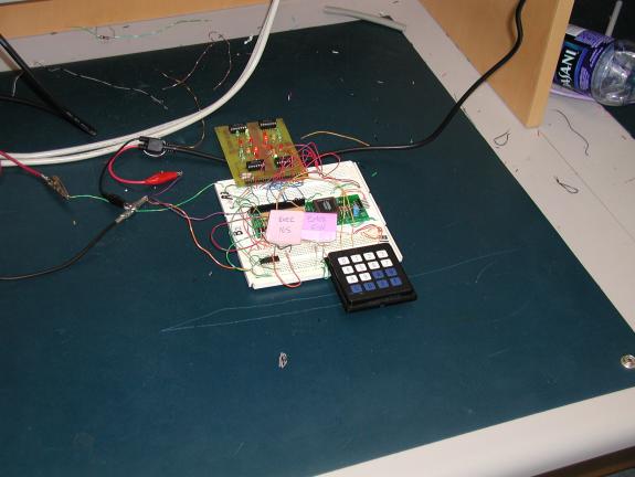
Prototype:
Conclusion:
The Opticom priority control
traffic system produced results which were satisfactory for the project at
hand. It simulated a traffic light
intersection and took care of emergency vehicles approaching. Minor improvements could have been made such
a delay between the lights and including more cases such as night-time driving
and a pedestrian crossings. However,
this system is very practical in the real world. Slowly, cities are taking
advantage of these products from companies such as 3M. All in all I feel that this project was
success and it was great example in combining both courses.