Morse Code Transmitter
PC300/PC319 Project by Jonathan Cerantola & Craig MacIntosh
Here is our beautiful circuit. Click for a larger picture.
Introduction
The purpose of this project was to design and build a Morse code transmitter that takes input from a keyboard and outputs the Morse code signal to a speaker.
The components used in this project include: PS/2 Keyboard, speaker, CPLD, 7408 chip (AND gate), wave generator, and a 200 ohm resistor.
Back to the Top
Block Diagram

VHDL Code
Decoder.vhd -- This is the main code that makes all the components work together, etc...
Stop.vhd -- This is the code for converting the serial data in from the keyboard to parallel data (a 7 bit binary number that represents a letter).
Pdatahold.vhd -- This code holds the parallel data.
Letters.vhd -- This code takes the 7 bit binary number that represents a letter and outputs the correct Morse code for the letter inputted.
Soundout.vhd -- This code is used by the Letters.vhd. It is for outputting either a short pulse or a long pulse.
Back to the Top
Simulation
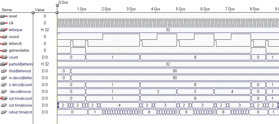
This is the waveform output of the Decoder.vhd simulation. The important parts to notice is the letterpar input which is the letter B, or 32 in hexidecimal. The sound output shows a long pulse followed by three short pulses, which is the correct Morse code output for B.

Simulations for all vhd files in scf format:
Back to the Top
Circuit Description
A letter is inputted from a PS/2 keyboard into the CPLD. The CPLD converts the input from serial data into parallel data, each letter has a 7 bit binary number. The CPLD then decodes the 7 bit binary number and outputs the corresponding Morse code output for the particular letter as a series of 1's and 0's. The output of the CPLD is run through a 200 ohm resistor to reduce noise, and is ANDed with the output of a wave generator, the output of the AND gate is fed into a speaker which outputs a series of short and long beeps for the letter that was inputted.
Back to the Top
Results
The results for this project were mixed. The compilation and simulation of our VHDL code turned out fine. But, due to the small size of the CPLD and the length of our VHDL code we were unable to fit all of the letters into the CPLD, we could only fit the coding for three letters in. Also, we could not get the keyboard to input properly, this was possibly due to the timing of the clocks and the serial to parallel data conversion code. However, if a letter was held down long enough the correct output would be heard. When the debugger board was used to input the letters we got the correct output, so we know that the decoding and output portions of our code worked correctly.
Additional Info
| Letter | Hex (AT Keyboard) | Binary (AT Keyboard) | Morse Code Output |
| a | 1C | 0011100 | .- |
| b | 32 | 0110010 | -... |
| c | 21 | 0100001 | -.-. |
| d | 23 | 0100011 | -.. |
| e | 24 | 0100100 | . |
| f | 2B | 0101011 | ..-. |
| g | 34 | 0110100 | --. |
| h | 33 | 0110011 | .... |
| i | 43 | 1000011 | .. |
| j | 3B | 0111011 | .--- |
| k | 42 | 1000010 | -.- |
| l | 4B | 1001011 | .-.. |
| m | 3A | 0111010 | -- |
| n | 31 | 0110001 | -. |
| o | 44 | 1000100 | --- |
| p | 4D | 1001101 | .--. |
| q | 15 | 0010101 | --.- |
| r | 2D | 0101101 | .-. |
| s | 1B | 0011011 | ... |
| t | 2C | 0101100 | - |
| u | 3C | 0111100 | ..- |
| v | 2A | 0101010 | ...- |
| w | 1D | 0011101 | .-- |
| x | 22 | 0100010 | -..- |
| y | 35 | 0110101 | -.-- |
| z | 1A | 0011010 | --.. |
| backspace | 66 | 1100110 | ........ (to indicate a mistake) |
| space | 29 | 0101001 | (7 blank units) |
The pins for the PS/2 Keyboard are:
1. DATA
2. No connection
3. GND
4. +5V
5. CLK
6. No connection
The PS/2 is numbered as follows:
^
6 5
4 4
> 2 1 <
Links