Constant Illumination Circuit
using triac controller in delayed trigger mode
Date Last Modified: Dec 1, 2001
Group : Jeff Giles and Geordie Schell
General Information
Circuit:
This circuit will dim or brighten a lamp as ambient light changes to provide a constant light level. The main interfaces are the light sensor, the lamp plugged into the TRIAC controller box, and the adjustable control resistor Rc. As ambient light increases the light sensor detects this and the lamp dims, to maintain constant light. The control resistance Rc is used to vary the level of light to be maintained; as the resistance is increased the light level to be maintained will be lower, ie the lamp will be less bright for a given ambient light level.
Circuit Picture
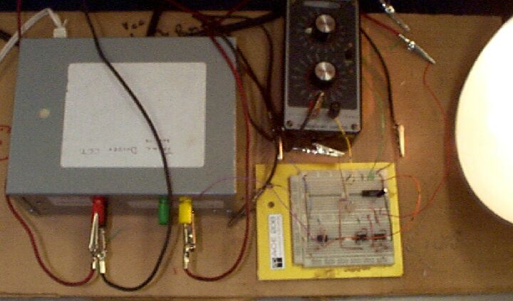
Pictured is the Triac box (left, containing the triac controller and zero crossing detector), controlling resistor (middle top), bread board (middle bottom, containing opamps, one-shot, photoresistor and capacitor). Also pictured is the light bulb on the far right. It is receiving full AC power since the picture was taken in a dark room (camera flash makes ambient light levels appear to be higher).
Triac:
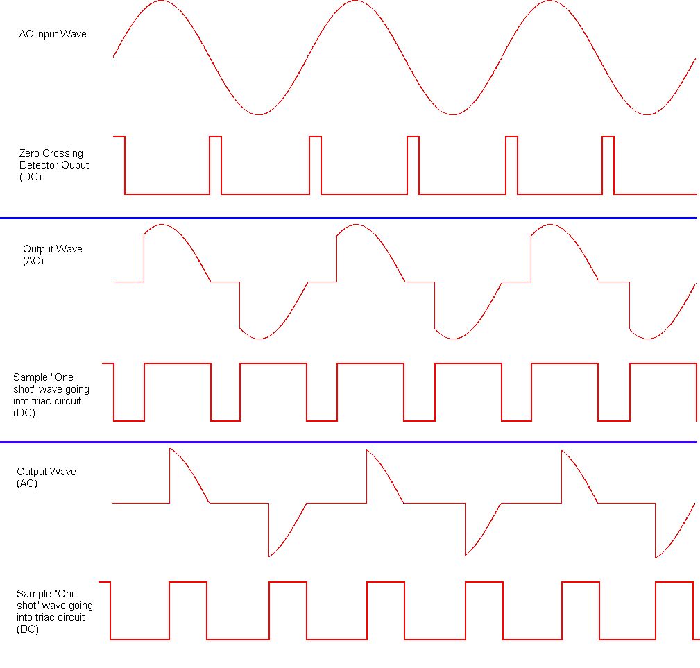
The triac controller switches AC by means of a controlling DC current; when a gate pulse is recieved at the control input the AC is switched on for the rest of the duty cycle, when the current is 0 the unit switches off. The Triac box we used has a zero crossing detector which
produces a short pulse when the AC waveform crosses the 0 point. When operating in Delay/Trigger mode the output of this zero crossing detector is directed through some sort of device which will delay the triggering of the triac controller. By delaying the pulse by a specified time the amount of the AC wave form which is ON can be modulated, refer to the timing diagram for details.
Timing Diagram
How we made it work:
Obviously we wanted the triac to be working in delay/trigger mode, which provides a slick dimmer switch like effect. We implement delay/trigger mode with a one-shot circuit. Every time a pulse is received (from the Zero Crossing Detector, indicating the AC waveform has crossed 0v) the one shot holds the pulse for a specified length of time, determined by the values of Rext and Cext. The timing equation for the pulse width of the one shot is Tw = K*Rint*Cext where Tw is in nano seconds, Rint is in KOhms, and Cext is in picoFarads. We decided to use a fixed capacitance and resistance and to modulate the voltage accross the timing components. In this way a smaller voltage across the components will make them bahave very much like there is a larger resistance; thus we get a wider pulse width when the voltage is small. You may be asking yourself, why does this matter? The TRIAC is still going to trigger when it receives an upward going transition, isn't it, and once that happens the AC is ON for the rest of the duty cycle, so what's the point of varying pulse widths? Well if we use the inverted oneshot output we can get the pulse going to the triac to be high at different points in the AC duty cycle, this gives us the desired result of dimming the light.
Schematic Diagram
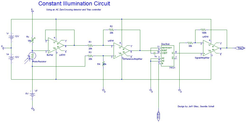
Schematic Explaination
The above schematic shows the circuit used to modulate the AC wave form. The main part of this circuit is the 74121 One-Shot, this device is used to control the TRIAC box which in turn makes the light dim/brighten. The one-shot itself is controlled by the "Cext" and "Rext" connected to it, these components control the timing of the one shot. We modulate this timing network by means of a voltage divider (the photoresistor and variable resistor at right). This voltage is put through a buffer (doesn't affect anything in the circuit), and then through a Difference Amplifier. The purpose of this is to subtract the voltage of the voltage divider from 5v thus making a small voltage a big voltage (between 0 and 5v) and vice-versa. This output is then fed into the internal resistance of the one-shot, thus determining the output width of the one-shot pulse. Note that as the photo-resistance increases the the voltage in the divider decreases.
Links
These should hopefully clarify any information we forgot to mention
More info about using photoresistors and voltage dividers
More information on Opamps
Datasheet for u741 Opamp
Datasheet for the 74121 One Shot