Figure 1: Bouncing Ball Timer
Design Specification:
The project we chose is the Bouncing Ball Timer. Basically, the circuit takes an accurate reading of how long it takes a ball to fall a certain distance. What happens is a solenoid is attached to a lever that is holding a metal ball over a pressure sensor. To release the ball, you must generate a magnetic field in the solenoid (in effect turn “on” the solenoid). Once the magnetic field is created, the lever is pulled up and tips the ball which then drops towards the pressure sensor. As soon as the solenoid is turned “on” the counter begins. The counter stops once the ball lands on the pressure sensor. When this happens the time is displayed, which is accurate to three decimal places, on our 7-segment displays.
The Inputs and Outputs for the circuit are as follows:
Inputs:
Ball Release Button – releases the ball from the solenoid and starts timers.
Reset Button – resets the timer and turns “off” the solenoid so it can hold the ball.
Pressure
Sense – this stops the counting.
Outputs:
Output_ds, Output_cs, Output_ms – displays the time on a couple of 7- segment displays
Solenoid – This turns the solenoid on to release the ball.
Figure 2 represents the Block Diagram of the circuit. It shows the key components and the basic layout. It also shows the inputs and outputs and the direction the current and voltage flows with respect to each one.
Figure 2: Block Diagram of Bouncing Ball Timer
Schematic and Timing Diagram:
Figure 3 is the Schematic Diagram for the circuit. It shows the pin outs and the different components uses. Figure 4 is the Timing Diagram for the VHDL code used in the CPLD.
Figure 3: Schematic Diagram of circuit showing the various components and pin outs.
Figure 4: Partial Timing Diagram for Circuit. Click here for rest full timing diagram.
Circuit
Description:
For the purposes of this section, this document will look at the three different states of this state machine. The three states are idle, counting and display. Figure 5 represents the State Diagram, which describes what happens in the Complex Programmable Logic Device (CPLD). To see the VHDL code that was used to create this state diagram click here.
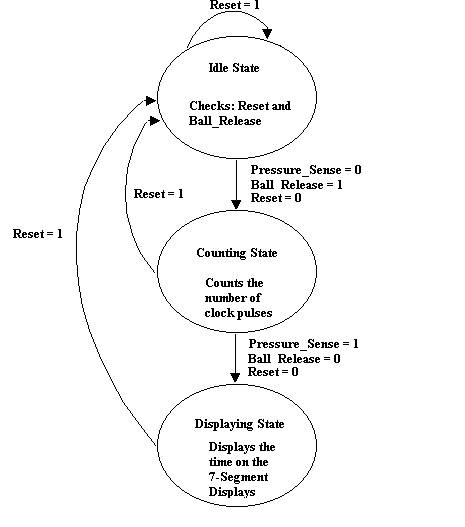
Figure 5: State Diagram showing what happens in the CPLD.
Idle:
When the device is turned on the circuit is in the idle state. In the idle state there are two different statements, one being the reset and the other being the Ball_Release. If reset is set to a ‘1’, which is achieved by pressing button number 0 on the keypad of the system, the solenoid is turned off and all the internal counting signals are set to ‘0’. On the other hand if the Ball_Release input is set to ‘1’, which is achieved by pressing the number 4 on the keypad of the system, the solenoid output is set to ‘1’ and the state changes over to the counting state. The output to the solenoid does not have enough current. To rectify this problem, the signal is sent through a current amplifier. When the solenoid receives the logic high the ball resting on the lever is dropped towards the pressure pad below.
Counting:
After the state changes over to the counting state, the user can reset the system, which would bring it back to the idle state, or it can count the time. If the Pressure_Sense input is ‘0’ then the ball is still free falling towards the sensor. As the ball is falling the internal signals, Count_ds, Count_cs and Count_ms, are being used to count the clock pulses from the wave generator (clk). The system stays in the counting state until the Pressure_Sense input sends a pulse of ‘1’, meaning that the ball has hit the sensor. The signal that is generated by the pressure sensor is not strong enough for the CPLD to recognize a logic high. So, an Op Amp that amplifies the signal by ten was used to solve this problem. Now that the ball has hit the pad the system changes over to the display state.
Display: