|
Specification
Controller:
The Controller will produce 2 analog signals, one for each
motor, and a digital abort signal.
The Encoder:
The Encoder receives the 2 analog signals and converts them
into 3-bit digital signals which are fed into the Flex chip.
The abort signal from the controller is passed to the Flex
chip.
The Flex Chip:
The Flex chip receives 2 3-bit signals, one for each motor.
Each of these signals drives a state machine which will
produce pulses of varying width every 20 ms.
These pulses will be fed to the two servo motors of the
robot. The abort signal will disable the production
of the pulses for as long as it is held high.
Block
Diagram

Circuit
Description
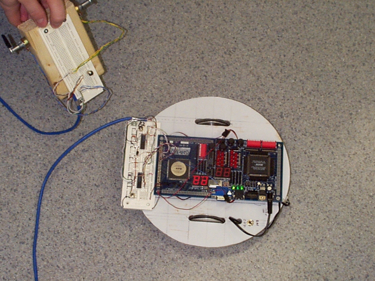
Controller:
The controller is composed of
2 potentiometers, as well as the abort button. The potentiometers
produce analog signals (for left and right wheels respectively),
which are passed to the encoder. Each potentiometer
is connected between power and ground (which come from the
encoder) and will produce an analog signal between 0 and
5 V. Each potentiometer has 3 pins: 5V power, the ground
and the analog output signal. The abort signal (active high)
is also passed to the controller, for relaying to the Flex
chip. The abort signal is controlled by a normally off button
between power and the output pins. The abort output is in
the high impedance state when the button is not pressed.
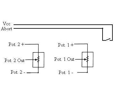
Encoder:
The encoder receives the abort
signal from the controller. This signal is connected
to ground through a tie down resistor and to the abort input
on the Flex chip. The tie down resistor pulls the
signal being passed to the Flex chip low when the abort
signal received is in the high impedance state. When the
abort signal received is high, it is simply relayed to the
Flex chip.
The encoder receives the analog
signals from the controller and encodes them into 8 bit
digital signals, of which the 3 most significant bits are
relayed to the Flex chip. An ADC0804 chip is used to encode
each of the analog signals. The power pin of each
of the potentiometers is connected between the power and
the Vcc pin on the respective ADC chip. The ground
pin of each potentiometer is connected between ground and
the V- input on the ADC chip. the output pin of each
potentiometer is connected to the V+ input of the respective
ADC. The Vref/2 of each of the ADC chips is connected
to a voltage reference diode (lm336 2.5), supplying 2.5
V. The same lm336 chip supplies both ADCs. The CLK R pin
of each of the ADCs is connected to ground through a resistor
and a capacitor, while the CLK In pin is connected between
the resistor and capacitor to run the ADCs in the free running
mode. When each of the ADCs is initiated, INTR and WR inputs
must be tied low momentarily and then the WR input must
either go high or float. The RD input must be tied low for
the ADc to return the digital result. The INTR and WR inputs
are tied together on each chip. A normally off button connecting
the INTR and WR inputs to ground was used for this purpose
(i.e. the button was pressed when the circuit was first
powered on).
Flex:
The Flex chip receives 2 3-bit
inputs (6 inputs altogether) and the abort signal. The 3-bit
signals are sampled by the PLD and drive the state machine.
The state machine (see VHDL code) generates 2 sets of pulses
(1 for each servo) which occur every 20 ms. The width of
these pulses (again set by VHDL code depending on the digital
signal received) control the speed the servos rotate at.
Schematic
Design
Controller:
Encoder:
VHDL
Code and other files
VHDL Code for state
machine
Symbol
file for state machine
Graphical
Editor file for FLEX Chip
Partial
Simulation with 25 MHz clock (zip file)
Full
scope simulation with only 1 MHz clock showing (zip
file)
VHDL
code that produces the above simulation (25 MHz clock
taken out)
Links
to component Datasheets
Altera
University Program Design Laboratory Package Datasheet
ADC0804
Datasheet
LM
336 Datasheet
|