![]()
![[WLU Physics!]](webpag5.gif) Proud
Supporters Of WLU Physics
Proud
Supporters Of WLU Physics
Bouncing Ball Timer
Andrew Adams,
990952140
Ian Lochbihler, 991808160
Table Of Contents
Circuit Overview
Design Description
Design Specification
Inputs
Outputs
Block Diagram
Structured Logic Device
Description
State Diagram
State
Table
VHDL
Code
Timing Diagram
Schematic Diagram
Major Circuit Components
PLD-44
Programmable Logic Device
Solenoid
Keypad
Sound Receiver
(Current Modulator)/Pressure Sensor
7-Segment
Displays
Transistor Package
Logical
Circuits Built
10ms Clock
Start-Release-Stop
State Machine
Transistor Array
Prototype
Problems & Solutions
Conclusion
Glossary
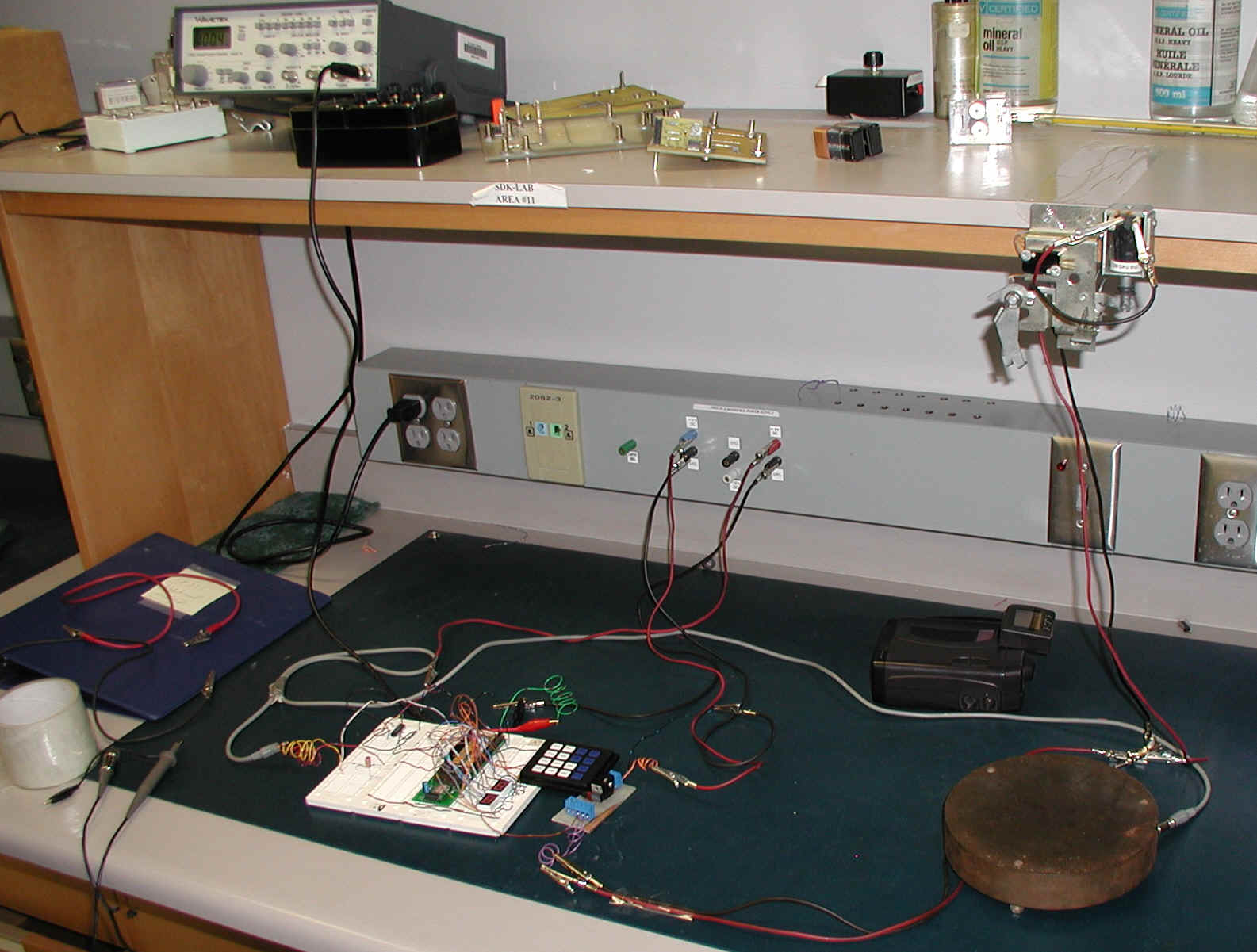
Our goal was to build a circuit which could measure the time taken for an object to fall a given distance.
The bouncing ball timer uses a solenoid to hold a ball
above a pressure sensor. When the start button is depressed and in the idle
state, the ball is released, the system is changed to the falling state and the
PLD starts counting the clock pulses that are formed by a wave generator.
Once the ball reaches the pressure sensor, the system changes to the landed
state and stops counting the clock pulses. The time it took the ball to fall is
calculated to the nearest hundredth of a second and in outputted to two
7-segment displays. When the start button is depressed it send a voltage pulse
to the solenoid and the PLD to activate them. When the pressure sensor is
struck, it sends a voltage pulse to the PLD deactivate the counters. When the
reset button is depressed, the system is forced back to the idle state and the
displays are reset to read 00. Since the wave generator is ran at 100 Hz, each
clock pulse represents 0.01s.
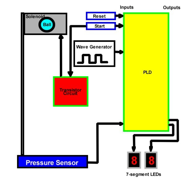
The bouncing ball timer is a device that measures the
amount of time it takes for a ball to fall from a given height.
Inputs:
Clock – used to calculate the amount of time it takes for the ball to fall
from the solenoid to the pressure pad.
Reset – used to reset the timer display and the system.
Start – releases the ball from the solenoid and tells the PLD to start
counting the clock pulses.
Hit – tells the PLD to stop counting the clock pulses when the ball reaches
the pressure pad.
Outputs:
T1 – the amount of time it took for the ball to fall from the solenoid to the
pressure pad with respect to the hundredth of a second place.
T2 – the amount of time it took for the ball to fall from the solenoid to the
pressure pad with respect to the tenth of a second place.
Block
Diagram:
| |
|
HIT
/ START / RESET |
|||||||
| |
|
000 |
001 |
010 |
011 |
100 |
101 |
110 |
111 |
| IDLE |
00 |
00 |
00 |
01 |
00 |
00 |
00 |
01 |
00 |
| DROPPING |
01 |
01 |
00 |
01 |
00 |
10 |
00 |
10 |
00 |
| HIT |
10 |
10 |
00 |
10 |
00 |
10 |
00 |
10 |
00 |
| |
|
S* |
|
|
|
|
|
|
|
LIBRARY IEEE;
USE IEEE.std_logic_1164.all;
use IEEE.std_logic_unsigned.all;
ENTITY project IS
PORT(start, reset, clk, hit : in
std_logic;
t1, t2
: out std_logic_vector (6 downto 0));
END project;
ARCHITECTURE stuff of project is
type state_type is (idle, dropping, landed);
signal state: state_type;
signal c1, c2 : std_logic_vector (3 downto 0);
BEGIN
PROCESS
(clk)
BEGIN
if (rising_edge(clk)) then
if reset = '1' then
c1 <= "0000";
c2 <= "0000";
t1 <= "0111111";
t2 <= "0111111";
state <= idle;
else
case state is
when idle =>
if reset = '1' then
state <= idle;
elsif start = '1' then
state <= dropping;
else
state <= idle;
end if;
when dropping =>
if c1 = "1001" then
c1 <= "0000";
c2 <= c2 + '1';
else
c1 <= c1 + '1';
end if;
if reset = '1' then
state <= idle;
elsif hit = '1' then
state <= landed;
else
state <= dropping;
end if;
when landed =>
case c1 is
when "0000" => t1 <= "0111111"; --0.x0
when "0001" => t1 <= "0000110"; --0.x1
when "0010" => t1 <= "1011011"; --0.x2
when "0011" => t1 <= "1001111"; --0.x3
when "0100" => t1 <= "1100110"; --0.x4
when "0101" => t1 <= "1101101"; --0.x5
when "0110" => t1 <= "1111100"; --0.x6
when "0111" => t1 <= "0000111"; --0.x7
when "1000" => t1 <= "1111111"; --0.x8
when "1001" => t1 <= "1100111"; --0.x9
when others => t1 <= "1111001"; --0.xE
end case;
case c2 is
when "0000" => t2 <= "0111111"; --0.0x
when "0001" => t2 <= "0000110"; --0.1x
when "0010" => t2 <= "1011011"; --0.2x
when "0011" => t2 <= "1001111"; --0.3x
when "0100" => t2 <= "1100110"; --0.4x
when "0101" => t2 <= "1101101"; --0.5x
when "0110" => t2 <= "1111100"; --0.6x
when "0111" => t2 <= "0000111"; --0.7x
when "1000" => t2 <= "1111111"; --0.8x
when "1001" => t2 <= "1100111"; --0.9x
when others => t2 <= "1111001"; --0.Ex
end case;
if reset = '1' then
state <= idle;
else
state <= landed;
end if;
end case;
end if;
end if;
end
PROCESS;
END stuff;
PLD-44
Programmable Logic Device
The PLD is used to store our VHDL program and perform all of our logic.
It houses the counters for the clock, controls the state and monitors the inputs
and outputs of the system.
Solenoid
The solenoid holds the metal ball in place until the start button is depressed.
Keypad
The keypad is used as an input device for the PLD. It controls the inputs that
allow a change of state. These inputs include: reset and start.
Sound Receiver (Current Modulator)/Pressure Sensor
This current device sends a pulse to the PLD when the ball hits it. It controls
the landed state and triggers the output to the display.
7-Segment
Displays
These displays show the total amount of time it takes for the ball to fall from
the solenoid to the pressure sensor. The tenth of a second digit is outputted to
one display and the hundredth of a second is outputted to the other.
Transistor Package
This package was made to conquer a lack of current problem. The solenoid needs a
lot of current to trigger so this packages allows the solenoid to be powered by
a separate 12V source while the rest of the circuit functions off of a 5V
source.
10ms
Clock
The clock input was driven by a wave generator functioning at 100 Hz. This
produced pulses with a width of 10 ms. The PLD counts each of these pulses
during the fall of the ball.
Start-Release-Stop State Machine
The system has 3 states, reset overrides any state to return the system to idle.
The other states are triggered by various inputs.
Transistor Array
In theory, there was enough current to drive the solenoid and produce a
logic high on the PLD when the start button was depressed. In practice, only one
of these functions could be done at the same time. Since the solenoid needs a
lot of current to function, we elected to drive the solenoid with a 12V source.
This also allowed us to continue powering the rest of our circuit with 5V which
is needed for our TTL logic. We needed to drive the solenoid with out 5V input.
This is achieved through an array of transistors using a 5V trigger on the base
and 12V inputs. When the signal is high, the 3904 transistor will allow the 12V
to flow from emitter to collector. This produces a voltage on the base of
the 3055 transistor and allows the voltage to flow from emitter (solenoid) to
collector. This flow triggers the solenoid and the ball is dropped. The circuit
can be seen in Figure 1-1 below.
See Figure 1-2.
In this circuit, the start button releases 5 volts to perform two tasks:
a) Activate the solenoid
to release the ball
b) Send a message to the PLD: "start counting!"
In observation, an error was occurring at this stage. It was then discovered that the solenoid drew so much current, and by Ohm's law (V=IR) was not leaving enough voltage to trigger the PLD. We solved this problem by wiring a second power supply to what was essentially a 'voltage gate' - the start button was then connected in such a fashion that it would allow 5V to trip the PLD and activate the voltage gate simultaneously, so that the two tasks were accomplished independently of each other.
This PLD based circuit produces results very close to the expected value. All of our results fell within 5% of the expected value. This error can be attributed to friction in the solenoid, air resistance, and delay in the logic gates/solenoid/PLD. To solve the current draw of the solenoid we implemented a second voltage with an array of transistors. For a production circuit, we would want to produce a solenoid that held the ball with better accuracy or one that used a magnetic field to hold the ball, this would reduce the amount of error. Also, gravity could be calculated from this circuit if the user were to input the distance the ball fell.
Glossary:
7 Segment Display - See LED.
Clock - A basic counter device.
Current - The flow of electricity, measured in amperes.
Current Modulator - A device which uses magnets to interact with a current when sound is made. Also known as a Microphone, speaker, etc.
Gravity - The constant 9.8m/s/s on Earth.
LED - Light Emitting Diodes are used in this project to display time. In this configuration, they are cut into 7 bars each which can be active independently, to make up a number from 0 - 9.
PLD - Programmable Logic Device
State Machine - Used to describe a system with changing, dynamic states; eg. Active & Not-Active.
Solenoid - A magnetic bar enclosed by a wrapped coil, based on the interaction of magnetic and electric fields. When a current is passed through the coil, the bar is forced to move.
Transistor - A device composed of semiconductor material that amplifies a signal or opens or closes a circuit, like a switch.
Wave Generator - A device which can create a user-defined electrical wave function, based on the fundamentals.
VHDL - Hardware design language created by the DOD and IEEE.
Voltage- The measure of the pressure difference of electricity (EMF or Electro-Motive Force). The pressure required to force one ampere of current through a resistance of one ohm.
Posted: Sun Dec 2 12:59:34 EST 2001
Copyright 2001© Ian & Andy Co.