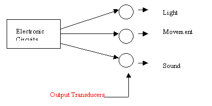
A device which can convert information from one physical form to another.
Electrical systems are only able to respond to voltage and current signals in the electrical domain: amplitude, frequency, phase and time constant.
A transducer may generate an electrical signal by varying one of the following: voltage, current, resistance, capacitance, self-inductance, mutual inductance. The most fundamental transducers respond to temperature, electromagnetic radiation intensity, force, displacement or chemical concentration. If coupled to the time domain these devices can be used to measure any physical or chemical quantity.The output transducer transfers signals out of the electrical domain and into the domain that can be perceived by one of the five human senses. A substantial amount of power is usually required to transfer information out of the electrical domain.
An output transducer can:

- e.g. heater, light bulbs
- e.g. solenoids, motors.
- have to worry about back EMFs.
Consider:
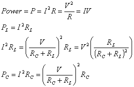
For proportional control, need to be able to dissipate as much power in control as in load! Therefore, not efficient.
Can turn ON/OFF quickly to approximate proportional. This can produce noise, especially with inductive loads.
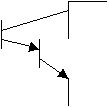
Current Device: current going in the base matters
Modes of Control
Burst mode - turn on at zero
crossing, slow rate but smooth, used for electric heaters
Delayed Trigger - turn on during cycle, fast
rate and starts up high at instant turn on, used for lights
Application of power-control circuit
Switching circuits
Circuits designed to respond to nonlinear waveforms, such as square waves are referred to as switching circuits. These switches are commonly used as drivers in switching applications. A driver is a circuit used to couple a low-current circuit output to a relatively high current device, such as an LED.
The BJT as a Switch
A bipolar junction transistor (BJT) is a current-controlled device, the base current controls the amount of collector current. It can be used as a switch by driving the component back and forth between saturation and cutoff. A basic transistor switching circuit is shown in figure (a). The way this is accomplished is easy to see if you refer to the dc load line shown in figure (b).
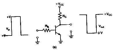
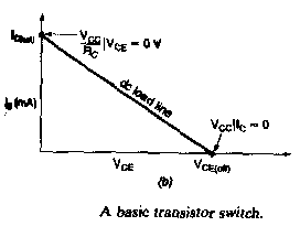
when the input to the transistor is –V, the emitter-base junction of the transistor is biased off. When the transistor is biased off, the following condition exist:
Vce =Vcc (ideal) and Ic =0 (ideal)
As figure 2 (a) shows, these conditions are the same as those caused by an open switch.
When the input to the transistor is at +V, the transistor will saturate. This assumes, of course, that the input current is sufficient to cause saturation. When the transistor saturates, the following condition exists:
Vce=0V(ideal) and Ic=Vcc/Rc (ideal)
As Figure 2 (b) shows, these conditions are the same as those caused by a closed switch.
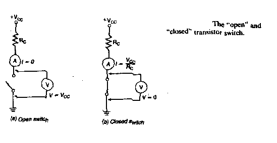
The high input voltage, +Vin must ensure that the transistor saturates, In a practical transistor switch , this is accomplished by two thing:
This equation can be rewritten to give us equation for Vin as follows:
Vin=IbRb+Vbe
For practical output values for a BJT switch, the output will never actually be 0V
The JEFT as a switch
The junction field effect transistor(JEFT) is a type of FET(a voltage-controlled device in which the voltage terminal controls the amount of current through the device) that operate reverse-biased junction to control current in a channel.
The basic JEFT switch differs from the BJT switch in several aspects:
Controlling external circuits
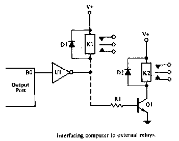
Certain calculation or signal-processing chores can be performed in the machine and then used to control external circuits. The simplest forms of external are on-off switches that are controlled by a single bit of a computer output port. More complex control applications use devices such as a amplifiers, DACs, and so forth.
Fig1-1 shows connecting the relay to the computer. Control over the relay is maintained by using 1 bit of the computer output port, in this case B0. Since only one bit is used, the other 7 bits are available for other applications, which may be displays, other relays, or certain other devices.
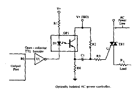
for interfacing the microcomputer with display devices as an oscilloscope or a strip chart paper record is shown in Fig 1-2. There are instances when these devices are the most appropriate means display, so we will want to provide some means to convert binary data analog voltages for the oscilloscope or recorder.
Simple Application
Model
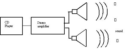
Taking into the audio scene, for a speaker, we have the input energy to be electrical, the loudspeaker as the transducer, which has the output energy of sound.

As stated from above, a loudspeaker is a transducer that converts electrical energy from an audio amplifier into mechanical vibrations of the air. That is it produces sound. This device is sometimes known as a dynamic loudspeaker or simply a speaker. The basic construction of a speaker is shown below.
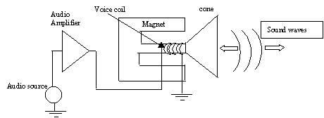
When electrical energy at audio frequencies, is applied to the voice coil, the magnetic field developed as a result, drives the cone in sympathy with the audio waveform.
The movement of the cone, backwards and forwards, produces a sound wave of which is a replica of the original electrical signal.
Loudspeakers have many uses including radios, sound systems and alarms.
References:
www.phys.ualberta.ca/~gingrich/phys395/notes/node152.html
www.swin.edu.au: Has another good application example of a light emitting diode.
Title: "Basic Operational Amplifiers and
Linear Integrated Circuits"
Author: Thomas L. Floyd and David Buchla of Yuba College
Date: 1999 edition
Created By:
Roshie Chadha, Jose Cisneros