PC/CP300 Electronics Laboratory II
Optoisolators Lab Requirements
Objective
Optoisolators, optocouplers, photo-isolated couplers, and photon isolators are different names for source/sensor pairs which are used to provide electrical isolation between two separate circuits. These circuits are completely separate and, typically, do not share a common power supply nor ground. An LED source is typically paired with a phototransistor, a photodiode, a light activated semiconductor relay or triac. A tungsten or neon lamp source is typically paired with a photoresistor.
- to investigate the concepts behind an optoisolator using an LED-photodiode source/sensor pair
- to use a commercial optoisolator
Equipment
- debugger board, bench supply, function generator, oscilloscope
- Green LED
- Photodiodes: Photoconductive, Photovoltaic
- Photodiodes: Osram SFH229
- Optoisolator: 4N26 - Fairchild, Isocom
Procedure
Photovoltaic and Photocurrent modes in a Photodiode
If you completed last week's lab, then you will have already done this part and can skip it.- Connect the photodiode to a voltmeter. You should see a
voltage which changes with the light falling on it. This is
photovoltaic mode of the photodiode. Consider
the
direction of the voltage to represent forward bias for
the photodiode.
You might not know that an LED can operate like a photodiode. Try the same thing you just did with an LED.
- Now wire up the photodiode in series with a decade resistor.
Apply power and ground so that the photodiode is in
reverse bias.
This is the photocurrent mode of the photodiode.
(Note that in this case, you may actually see a negative voltage across the pohotodiode at times due to the photovoltaic mode.)
- Measure the voltage across the photodiode as it is covered and
uncovered. Adjust the decade box to find what series resistance
maximizes the change in voltage from dark to light.
Demonstrate your results to the lab supervisor.
Creating an optocoupler
- A source/sensor pair can easily be made from individual components.
The diagrams below show a hand-made optoisolator using a green LED
source and a
photodiode and a sample circuit.
Although the diagram below shows the pair enclosed in heat shrink
tubing,
you will not use any enclosure.
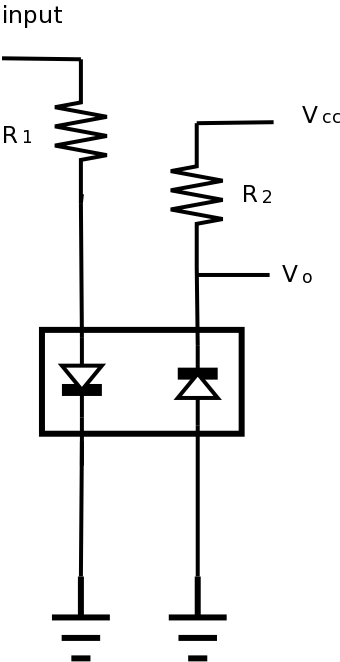
- Wire up the circuit as shown, using the resistance determined above (or whatever you have that is closest). Connect both the input and output to the oscilloscope.
- Now connect the LED and see if you can see the output voltage change as you turn the LED on and off. When you can, adjust the LED alignment with the photodiode to see if the response can be improved. What arrangement do you find optimal?
The control circuit should use input from the function generator; start with a slowly varying sinusoidal. Do not forget the current limiting resistor, R1, required by the LED.
The circuit under control is shown as a simple voltage divider.
Investigate the circuit operation for:- different separation distances between the LED and photodiode
- different frequencies
- different types of functions (triangle, square wave).
How does the signal change when you eliminate the ambient light by covering the optoisolator portion of the circuit with your hand (simulating the additional of an enclosure)? Why?
Demonstrate your results to the lab supervisor.
In order to show that the circuit works as expected, you'll need to display both the input and output at the same time.
Using a commercial optoisolator
- Look at the datasheet for the commercial optoisolator.
What is the source/sensor pair in the commercial component?
For information about photodiode/phototransistor equivalence, see www.electronicsarea.com/phototransistor.asp
- On the datasheet, find the recommended current
for the LED. Calculate the resistance needed to produce this
current with a 5 V input and use this for the input resistor.
Find the closest available resistor and wire this up.
-
Find the CTR (current transfer ratio) for the optoisolator
to determine the expected output current for the optoisolator.
Using a 5V supply and aiming for a 2.5V output determine the
resistance needed given the expected current.
Find the closest available resistor and wire this up.
In order to show that the circuit works as expected, you'll need to display both the input and output at the same time.
Make note of the resistance required.
- Once you are convinced that the commercial optoisolator is working
correctly, design a circuit using an optoisolator that will take
an input with Vcc of 12V and output to the LEDs on
a debugger board.
Demonstrate your results to the lab supervisor.


