PC/CP300 Electronics Laboratory II
Operational Amplifiers
Objectives
An operational amplifier or op-amp is a high gain DC amplifier typically used in a closed-loop configuration. The objectives for this lab are:
- to investigate two common closed-loop op-amp circuits: non-inverting amplifier, differential amplifier
At completion of the lab, you should have both a non-inverting amplifier circuit and a differential amplifier circuit on one breadboard. Do not dismantle these circuits. Store these circuits in your lockup area for use later. Since you are going to use these circuits in the coming weeks as a part of larger circuits, make sure you record all key connection points.
Equipment
- bench supply, oscilloscope
- function generator
- breadboard, variable resistor, resistors
- for non-inverting amplifier: LM324: data sheet from local server
- for differential amplifier: LM741: data sheet from local server
Procedure
You will be constructing two amplifier circuits on one breadboard; position your first circuit appropriately.
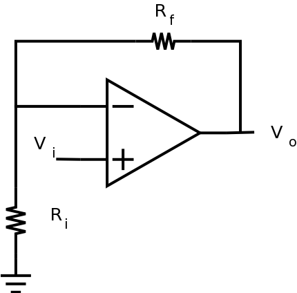
The non-inverting amplifier circuit to the left produces an output signal, Vo, that is given by
Vo = (Rf/ R1 + 1) VinSince the input does not enter the inverting input, the output signal will be of the same polarity as the input signal.
If we would like the above circuit to have a gain of ten, what are the relationships between R1 and Rf?
What is the smallest gain which can be produced by this amplifier?
When R1 is infinite, and Rf equals zero, what circuit does this become?
- Using the LM324, construct the
non-inverting amplifier circuit shown above subject
to the following constraints:
- gain is 10
- select resistors in the 1k to 100k range (record the actual resistor values for use in calculations)
- use ±12V for the supply voltages
- let Vin be 100mV
In order to show that the circuit works as expected, you'll need to display both the input and output at the same time.
Checkpoint: get lab supervisor to verify that you are getting the expected result before proceeding.
- Change the circuit from part 2 to drive Vin with a
1kHz, 1 Vp-p sine wave (verify
signal is correct before applying to the circuit). What
is the observed
maximum output swing? Why did I choose a 1
Vp-p signal rather than a
5Vp-p signal?
Adjust the amplitude and/or DC offset of the input in order to answer the following: What are the limits of the input voltage which produce an undistorted output?
- Change the circuit from part 3 to use supply voltages of
+7.2V/0V. (Single supply configuration).
As above, adjust the amplitude and/or DC offset of the input in order to answer the following: What are the limits of the input voltage which produce an undistorted output?
Is this consistent with the changes you made in the supply voltages?
The LM324 is known as a single supply op amp. Looking at your results, can you determine why it is designated that way? (Note: Any op amp can be used in either single supply or dual supply configuration, but there is a difference in how each will perform.) - Put a decade box (resistor) from the output of the op-amp to
ground. Set the initial resistance to at least 1 kohm or
so.
Observe the output and see how it decreases as the
resistance decreases. Find the value of resistance for which
the output is half of what it was originally. Determine
the current out of the op-amp for this resistance.
This gives a reasonable limit of the load which can be driven by the op-amp.
Demonstrate the non-inverting amplifier circuit to the lab supervisor.
In order to show that the circuit works as expected, you'll need to display both the input and output at the same time.
Keep the non-inverting amplifier circuit for future labs.
The differential amplifier circuit or difference amplifier circuit shown to the left (NOT to be confused with the differentiator circuit) produces an output voltage equal to the difference between the two input voltages.
Note the two voltage dividers in the circuit. In this circuit, typically, R1=R2 and R3=Rf so that the gain for the inverting and non-inverting inputs is the same.In the simplest case, Vo = Vin2 - Vin1 when the gain is one.
Using an LM741, construct the differential amplifier circuit on the breadboard that contains the summing amplifier circuit. Use ±12V for the supply voltages. Choose resistors in the 1k to 100k range to obtain a gain of 1. Drive Vin1 with a time varying signal and Vin2 with a constant voltage. Note the relationship between Vo and the inputs. What is the observed maximum output swing?
- Change the circuit from part 6 to get a nonunity gain.
What is the observed
maximum output swing?
Keep the differential amplifier circuit for future labs.
Demonstrate the differential amplifier circuit to the lab supervisor. Explain what gain you selected and how you obtained it.
In order to show that the circuit works as expected, you'll need to display both the input and output at the same time.
*** If you finish early, start on the postlab exercise. ***
Have the lab supervisor/demonstrator sign your lab notebook before you leave the lab.


