PC/CP300 Electronics Laboratory II

Introduction to Operational Amplifiers

Objectives

An operational amplifier or op-amp is a high gain DC amplifier; the operational portion of the name derives from its original application for performing mathematical operations in analog computers. The op-amp is an analog device that is very widely used in both analog and digital design because its operating characteristics can be significantly changed by connecting different external components.

The objectives for this lab are:

Equipment

Procedure

Notation and Terminology (no wiring in this section)

Use a 4 bus breadboard for this lab, so that you can have busses for both supplies, (positive and negative), as well as ground. Use appropriately colour-coded wires for these.

  1. opamp 
               symbol

    As shown in the diagram, the operational amplifier schematic symbol is a triangle and with at least two inputs and one output.

    Note that the two inputs are marked and behave differently.


    • The + input is the non-inverting or positive input of the op-amp. A signal applied to the non-inverting input is amplified by the op-amp.
    • The - input is the inverting or negative input of the op-amp. A signal applied to the inverting input is amplified and inverted by the op-amp.

    The inputs are not positional. Either input (inverting or non-inverting) can be the top or bottom input.


    For this lab you will be using the LM741 operational amplifier. Operational amplifier ICs are labeled with the manufacturer's prefix code, a three digit code indicating the type of op-amp, a letter indicating the operating temperature range, and a suffix code indicating the package type.

    Get a type 741 op-amp IC and open the data sheet for the 741.

    • What is the label stamped on the IC? What information does it tell you?
    • Sketch the pinout for the 741. Locate the inverting and non-inverting input pins and the output pin on the chip.

  2. Operational amplifiers are differential amplifiers; they amplify the difference in voltage between the signals at the two inputs (inverting input and non-inverting input). Therefore, if you shorted the inverting and non-inverting inputs together to ground, you would (ideally) expect an output of zero volts. In fact, an actual op-amp will probably have a slight offset at one of the inputs resulting in a non-zero output. This offset voltage will tend to introduce slight errors in an op-amp circuit.

    op-amp schematic 
		with offset null

    To allow for compensation of the offset voltage, some op-amps have two inputs that are called offset null inputs. If the circuit requires offset null inputs, the schematic will be as shown.

    If it is necessary to compensate for the offset voltage, short the inverting and non-inverting inputs together to ground and adjust the variable resistor until the output is zero. Then reconfigure the circuit as per the schematic leaving the variable resistor in the circuit as adjusted.

    Typically, we will not use the offset null inputs.

    Using the data sheet, locate the offset null pins on the 741 IC.

    Look at the schematic diagram of the LM471 internal circuitry on page 4 of the data sheet and locate the offset null inputs. Adding the offset null fine tunes the op-amp's internal circuitry since R1 and R2 are probably not identical.

  3. To recap:
    • The inverting and non-inverting input voltages (required) control the operation of the op-amp.
    • The offset null input voltages (optional) are used to fine tune the op-amp's internal circuitry for sensitive applications.

  4. op-amp supply voltage on 
		wiring diagram

    In addition, the op-amp IC has two inputs for power. These inputs are typically referred to as supply voltages or the rails. Typically, wiring diagrams will show the supply voltages and schematics will not show the supply voltages. The supply voltages are ALWAYS required when wiring up an op-amp even if not shown on the schematic.

    These inputs power the IC and limit the behaviour of the op-amp.


    • The inverting and non-inverting inputs should never be outside the supply voltage range.
    • The output voltage will never exceed the the value of the supply voltages.

    It is important to note that the supply voltages are indicated as positive and negative. The positive voltage supply must be greater than the negative voltage supply.


    caution!
    Precautions should be taken to insure that the power supply to the operational amplifier never becomes reversed in polarity. The input voltage at the positive supply pin must be greater than the input voltage at the negative supply pin. If polarity is reversed to the IC, the internal conductors can fuse and destroy the chip.

    The two most popular configurations for the supply voltages are:

    • dual supply, the voltages are the same value but opposite polarity
    • single supply, one voltage is ground and the other is a positive or negative voltage. (It's usually positive.)

    Using the data sheet, locate the supply voltage pins on the 741 IC. What is the polarity of the pins? How did you determine that from the data sheet (i.e. what notation did the data sheet use to indicate polarity)?

    If the opamp is configured using dual supply and the positive supply is +12V, what is the voltage on the negative supply? If the opamp is configured using single supply and the positive supply is +12V, what is the voltage on the negative supply?

  5. The most difficult thing about op-amps is the lack of consistency in the labeling conventions for operational amplifiers. Consider the following three diagrams. The first diagram shows the accepted terminology for the op-amp inputs and outputs.

    op-amp showing typical inputs

    The next diagram shows the notation used in the text; note that the supply voltages are never shown in the text and hence are not labeled in the diagram.
    op-amp 
	showing notation used by text

    The last diagram shows the notation used in the LM741 data sheet. For this figure where the output is simply labeled as "output", the correct notation in an equation would be Voutput to clearly indicate that this is a voltage. As an op-amp is always used as a voltage device, your notation when using equations should always express the inputs and outputs as a voltage. What notation would you use to represent the inverting and noninverting inputs in an equation?

    op_amp 
		showing LM741 datasheet notation

    Always check the reference's notation before blindly plugging in numbers into equations. It should be obvious from the above example why op-amp notation can be problematic.

    Demonstration: In a description of "Comparators", the general equation for the output of an op-amp is given as Vo = Av (V+ - V- ) where Av is the voltage gain. Rewrite this equation in notation appropriate to the LM741 data sheet. Explain your result to the lab supervisor.

    You must complete this demonstration before you apply power to any of the subsequent circuits.

The comparator - the op-amp in an open-loop configuration

Are you using a 4 bus breadboard?

  1. Operational amplifiers are differential amplifiers that amplify the difference in voltage between the two input connections or Vo = Av (V+ - V- ) where Av is the voltage gain.

    comparator with simple inputs

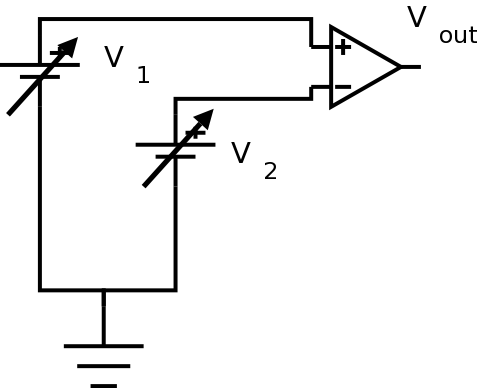
    Using the LM741, construct the open-loop comparator circuit shown. Be sure you use a 4 bus breadboard.
    Use ±12V for the supply voltages (note the above caution about polarity). Use the two variable dc supplies for V1 and V2. Monitor Vout with a digital voltmeter.
    caution Never apply inputs before establishing supply voltages.

    Sketch the circuit in your lab notebook. Since you will be doing a lot of circuit variations, it is important to get into the habit of always sketching the circuit in your lab notebook. Always include the supply voltages.


    1. Set V1 to 1 volt, and V2 equal to 0 volts. Note Vout.
    2. Increase V2 slowly to 2 volts, while watching Vout. Don't change V1.
      If you notice anything happen to Vout, record what happens and the value of V2.
    3. Now leave V2 at two volts, and increase V1 slowly to 3 volts, while watching Vout.
      If you notice anything happen to Vout, record what happens and the value of V1.
    4. Repeat the pattern of the last two steps, leapfrogging V1 and V2 until they reach the positive supply voltage. What pattern did you observe in Vout?

  2. Since Vo = Av (V+ - V_ ), what output would you expect if you had unity voltage gain, i.e. Av = 1? Explain.

    Knowing this, what can you say about Av for this op-amp, e.g. is it much less than 1, is it less than 1, equal to 1, greater than 1, much greater than 1? Explain your reasoning.

The voltage follower (buffer) - the simplest closed-loop configuration

The term open-loop comes from control system theory; in open-loop mode the control system has no feedback. Operational amplifiers are usually used in closed-loop mode where there is feedback from the output back to the input. All of the remaining op-amp circuits you will be investigating are closed-loop, although the term closed-loop usually does not explicitly appear in the name of the circuit.

comparator with simple inputs

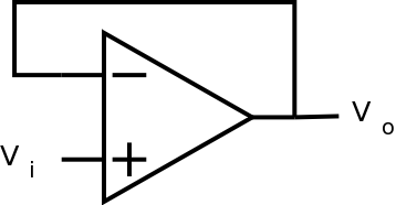
The voltage follower (or buffer) is a very simple circuit where the output should "follow" the input. In other words, Vout should equal Vin.

The inverting amplifier - one of the many closed-loop configurations


  1. inverting amplifier

    An inverting amplifier circuit produces an amplified output signal that is 180° out of phase with the input signal.

    Using an LM741, construct the closed-loop inverting amplifier circuit shown to the left. Use ±12V for the supply voltages. Use a feedback resistor, Rf, of 10 kOhms and an input resistor, Rin, of 1 kOhms. When you sketch the circuit in your lab notebook, note the feedback and input resistor values.


    In order to show that the circuit works as expected, you'll need to display both the input and output at the same time.

    Drive the amplifier with a 1 kHz sine wave with a DC offset of zero. Start with a small amplitude and increase the amplitude; note the signal behaviour as the amplitude increases. Sketch input and output; include measurements of amplitude.

    At what point does the signal saturate (output signal will no longer look like a sine wave)? For the remainder of this exercise, use a reasonable amplitude (not too small but do not saturate the output).

  2. Theoretically, Vo = Av (V+ - V_ ) where Av is the open-loop voltage gain. The closed-loop gain is a function of the feedback resistor and the input resistor. For the circuit in the previous question (nonsaturated state), what closed-loop gain did you observe? How does this relate to the resistors used in the circuit?

  3. What maximum output swing did you observe? What is this as a function of the rails?

  4. Since you know the equation (question 2) and you know the supply voltages you used, you can calculate the point at which saturation would occur, i.e. for what value of Vin? Show the calculation.

  5. Measure the voltage at the inverting input. Sketch the circuit and indicate how you are doing this measure.

    The inverting input is said to be at virtual ground. A virtual ground is a voltage ground because the point is at 0V; however, it is not a current ground because it cannot sink any current.

  6. Change the supply voltage to +5V/-12V. Sketch your circuit and show both the input and output voltages. Do you understand why the supply voltages are called the rails? Note the relationship of Vo to the supply voltages; does Vo reach the rails?

  7. Change the supply voltage to +7.2V/0V. (What is this configuration called?) Sketch your circuit and show both the input and output voltages. Is this consistent with what happened in the previous item? What does this illustrate about using inverting amplifiers in single supply configurations?

  8. Return to a supply voltage of ±12V. Try sine waves of different frequencies; at some point the amplifier will stop working properly. Note what happens and when it happens.

  9. What happens if you try different resistor values? Hold either the feedback or input resistor constant and change the other resistor. What is the relationship between the resistors and the gain? Do you see the voltage divider formed by Rin and Rf?

    Demonstrate the inverting amplifier circuit to the lab supervisor. Be prepared to explain the circuit's behaviour.
    In order to show that the circuit works as expected, you'll need to display both the input and output at the same time.
    You do not have to keep the circuit past the demonstration.
Have the lab supervisor sign your lab notebook before you leave the lab.

Resources

To view pdf documents, you can download Adobe Acrobat Reader .
get Acrobat Reader
If you need to update a browser, you might try Firefox which is Get Firefox!
Since this page uses cascading style sheets for its layout, it will look best with a browser which supports the specifications as fully as possible.

If you are looking for an office package, with a word processor, spreadsheet, etc., you might try LibreOffice which is Get LibreOffice!

Go to the main page for the Department of Physics and Computer Science.

Valid XHTML 1.1

Valid CSS!

WCAG
2.0
(Level AA)

Wilfrid Laurier University