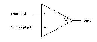
| Input Impedance | We will denote the input impedance as Zin. The input impedance of the opamp will be high if it doesn't draw alot of current. |
| Input Voltage | The input voltage of the Operational Amplifier is the original signal accepted by the Operational Amplifier for modification. The output voltage is denoted Vo throughout this lecture. |
| Output Voltage | The output voltage of the Operational Amplifier is the modified input signal. The modifications made to the input signal using the Operational Amplifier are and the result is referred to as the output voltage. |
| An ideal OpAmp will have a Zin that approaches infinity. This would imply that no current actually goes into the amplifier. Also, V- <= Vo <= V+ (the rails being the maximum and minimum output voltages.) An ideal OpAmp will have a Zout of zero. This would imply that the OpAmp can supply lots of current. The ideal OpAmp will have an Aol which approaches infinity and is independant of frequency. |
|
| Zin | Infinity |
| Zout | 0 |
| Aol | Infinity |
| In reality, OpAmps are not quite as elegant as Ideal OpAmps. Real OpAmps have predefined limits which allow limited possibilities of amplification and limits to the other various uses of OpAmps. The input impedance Zin of the Real OpAmp is typically some high resistance value. Typically, Zin is 2 MegaOhms for a Real OpAmp. | 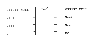 |
| Zin | 2 MegaOhms |
| Zout | 0 |
| Aol | 100000 |
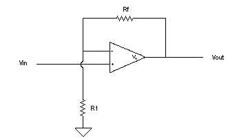
The equations for the non-inverting are as follows:   |
 |
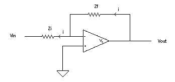
The equations for the inverting are as follows:  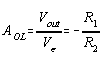 |
 |
| The equations for the Differentiator will be the inverse of equations made for the integrator. | 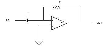 |
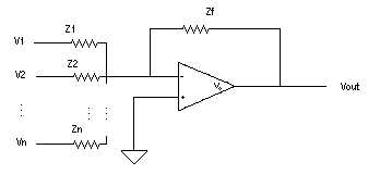
| The equations of the summing circuit are: Vo=(Zf/Z1)V1 + (Zf/Z2)V2 + (Zf/Z3)V3 + ... + (Zf/Zn)Vn |
 |
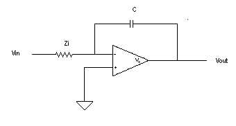
The equations for the Integrator circuit are: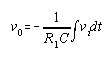  |
 |