V0 = Av ( V+ - V- ) = AvVd
| Input Impedance | We will denote the input impedance as Zin. The input impedance of the opamp will be high if it doesn't draw a lot of current. |
| Input Voltage | The input voltage of the Operational Amplifier is the original signal accepted by the Operational Amplifier for modification. |
| Output Voltage | The output voltage of the Operational Amplifier is the modified input signal. The modifications made to the input signal using the Operational Amplifier are and the result is referred to as the output voltage. The output voltage is denoted Vo throughout this lecture. |
| The operational amplifier can be regarded as the basic building block for
modern amplifiers. It is a high gain, integrated circuit amplifier designed
to amplify signals from d.c. up to many kHz. It is not normally used by
itself but with external feedback networks to produce precise transfer characteristics
which depend almost entirely on the feedback network. Usually there are
two input terminals and one output terminal, the voltage at the output terminal
being proportional to the difference between voltages at the input terminal.
An ideal OpAmp will have a Zin that approaches infinity. This would imply
that no current actually goes into the amplifier. Also, V- <= Vo <= V+ (the
rails being the maximum and minimum output voltages.) An ideal OpAmp will
have a Zout of zero. This would imply that the OpAmp can supply lots of
current. The ideal OpAmp will have an Aol which approaches infinity and
is independent of frequency. Typical maximum power supply voltages are +/-
15 V. Output voltage is typically confined to +/- 12 V, except "single supply"
types which can approach V- within 100 mV or so. The output voltage is a
function of the difference between the inputs.
V0 = Av ( V+ - V- ) = AvVd |
 |
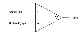
The following figure shows the circuit symbol and a simplified equivalent circuit for an operational amplifier.

| Zin | Infinity |
| Zout | 0 |
| Aol | Infinity |
| In reality, OpAmps are not quite as elegant as Ideal OpAmps. Real OpAmps have predefined limits which allow limited possibilities of amplification and limits to the other various uses of OpAmps. The input impedance Zin of the Real OpAmp is typically some high resistance value. Typically, Zin is 2 MegaOhms for a Real OpAmp. | 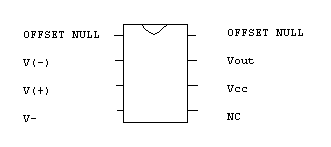 |
| Zin | 2 MegaOhms |
| Zout | 0 |
| Aol | 100000 |
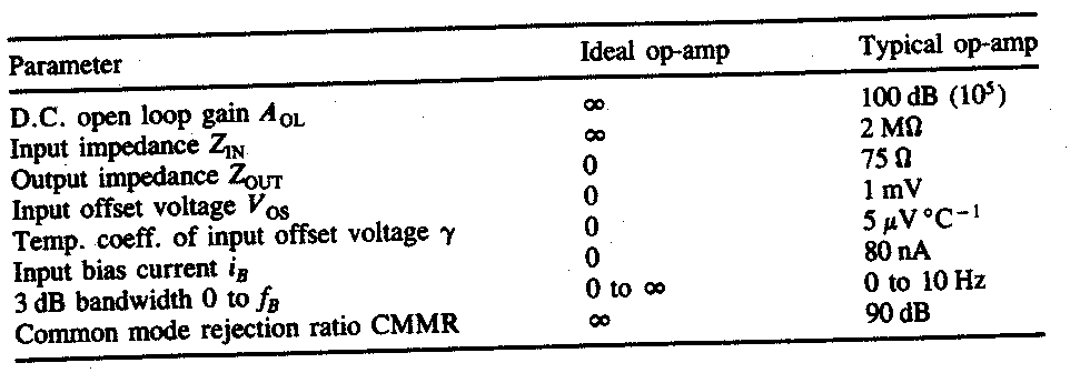
The following table summarizes the main characteristics of an ideal operational amplifier together with those of a typical real amplifier.
Typical Circuit Configurations
There are various circuits that can be constructed using OpAmps. Each
of these circuits has a unique function and special output characteristics.
For the following equations we used these two ideal conditions:
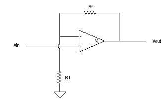
The equations for the non-inverting are as follows:  
|
 |
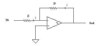
The equations for the inverting are as follows:  
|
 |
| The equations for the Differentiator will be the inverse of equations made for the integrator. | 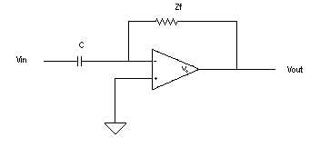 |
| The equations of the summing circuit are: Vo=(Zf/Z1)V1 + (Zf/Z2)V2 + (Zf/Z3)V3 + ... + (Zf/Zn)Vn |
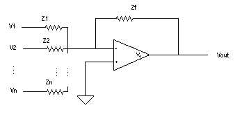 |
The equations for the Integrator circuit are: 
| 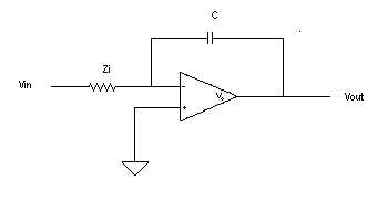 |
| The equation for the voltage follower is: Vout = Vin |
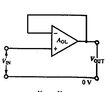 |
The a.c. performance of a practical operational amplifier is determined by
its dynamic characteristics. These are adequately represented by a first-order
lag, i.e.


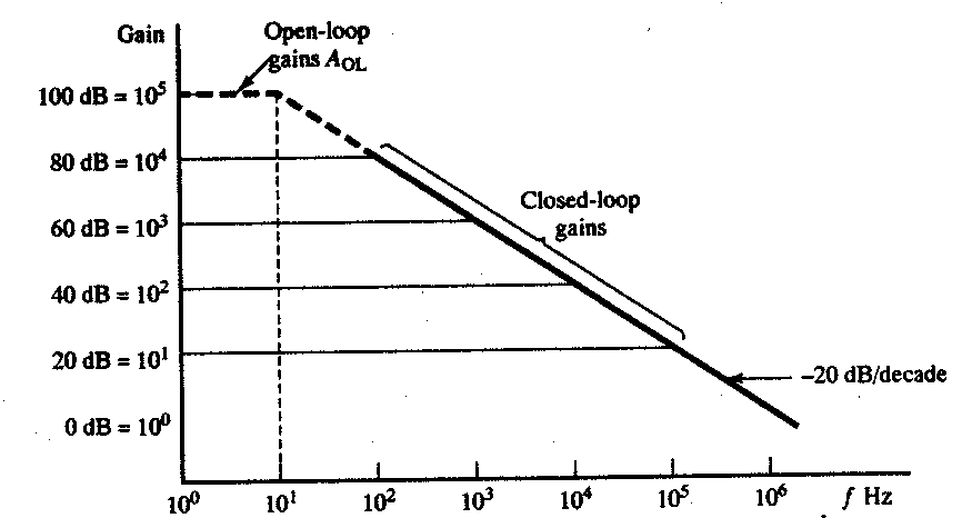
The following figure shows the variation in gain with frequency for both open- and closed-loop amplifiers. We note that the lower the gain of the closed-loop amplifier the greater the bandwidth. This is because the gain/bandwidth product of a closed-loop amplifier is also equal to the open-loop value of AOLfB.
