Resistors are components that resist the flow of electrical current or, in other words, resistors limit current. An ideal resistor obeys Ohm's Law, which states that the voltage (or potential) across a resistor is proportional to the current flow through the resistor. The ohm is a small value so usually you will be working in ohms, k ohms, or M ohms.
| Ohm's Law |
|
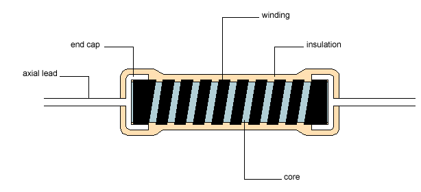
Typically, resistors consist of an nonconductive core (ceramic or glass rod) wound with a conducting material and covered with an insulating layer. The conducting material determines the resistor's operating characteristics and how it is wound determines the resistor's value. Carbon film is cheap but metal film or metal oxide allows for greater accuracy; these would be used in most typical circuit applications. Wire wound is extremely accurate and can be constructed for high current applications; these would be used in measuring equipment and power supplies.
Resistors come in many sizes, shapes, packages, and compositions.
An ideal resistor is characterized by its resistance measured in Ohms (e.g. 1.2 Ω or 1.2 Ohms). As it is not practical to manufacture every possible value of resistor, resistors are available in preselected ranges known as preferred values or standard values. The E12 series, which is the most common series, (12 values per 100) is denoted as: 10Ω, 12Ω, 15Ω, 18Ω, 22Ω, 27Ω, 33Ω, 39Ω, 47Ω, 56Ω, 68Ω, 82Ω. This does not limit the range of resistors to a total of twelve values, but each resistor value must begin with a number from the series and be multiplied by a power of 10, i.e. 1.5Ω, 15Ω, 150Ω, 1500Ω, 15000Ω, etc. The EIA standard values for E12, E24, E96,E192, can be found on every resistor manufacturer's web site.
Physical resistor components will vary from the ideal due to fabrication variability, resistor composition, and, over time, degradation due to aging. To characterize the resistor composition and fabrication variability, resistor manufacturers always specify a tolerance. The tolerance specifies the accuracy of the resistance as "plus or minus a given percentage of the nominal value". In other words, the tolerance is the maximum deviation allowed from the stated resistance value. For example, a resistor marked as 1.2 Ω ±10% has a nominal resistance of 1.2 Ohms, a tolerance of ±10% of the nominal resistance, and an actual resistance in the range
1.2Ω -10% to 1.2Ω +10%
= 1.2Ω - 0.12Ω to 1.2Ω +0.12Ω
= 1.08Ω to 1.32Ω.
If the tolerance is not specified, it is typically assumed to be ±20%. Tolerances expressed as a simple percentage, e.g. 10%, should always be interpreted as "±" the given percentage.
Note that the EIA standard values are related to the resistor tolerance: E6 (20%), E12 (10%), E24 (5%), E96 (1%), and E192( 0.5%).
|
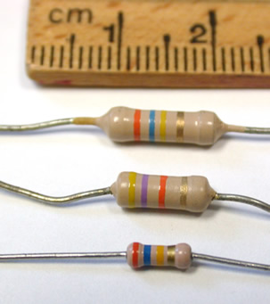
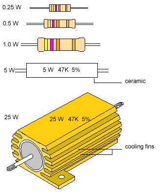
To ensure that resistors don't overheat, the resistor must have the correct power rating measured in Watts. power = P = V I = I2 R The more common ratings available for resistors are 1/8 Watt, 1/4 Watt, 1/2 Watt, 1 Watt and 2 Watt. For digital system applications, 1/4 Watt is typical. The power rating of a resistor indicates the resistor's ability to dissipate heat and keep its operating temperature within the resistor's operating range. If the temperature goes outside the operating range, the resistance of the component will change. To dissipate heat, the resistor uses surface area. Therefore, as the power rating of a resistor increases, the physical size of the resistor increases and the construction technique changes. The physical size of the resistor is not related to its resistance value. In the graphic to the right, all resistors have the same value and the same tolerance but range in power from 0.25W to 25W. The maximum rated power for a resistor is determined by the composition of the resistor. |
 |
Some composition resistors can be purchased with maximum-failure-rate guarantees. Failure rates are shown only on established reliability resistors and indicate the percent failure per 1,000 hours. For example, a 0.01 % failure rate would be interpreted as one resistor in 10,000 would fail per 1,000 hours.
The temperature coefficient of resistance (TCR) specifies the maximum change in resistance with change in temperature, measured in parts per million per degree Celsius (PPM/°C). To convert from PPM to %, divide the number of PPM by 10,000. For example, a TCR of 100 PPM/ºC is the same as a TCR of 0.01%/ºC. The temperature coefficient is only marked on more accurate resistors. For these resistors, resistors with temperature coefficients of 100 PPM/°C are the most popular, and will work for most reasonable temperature conditions. The others are specially designed for temperature critical applications.
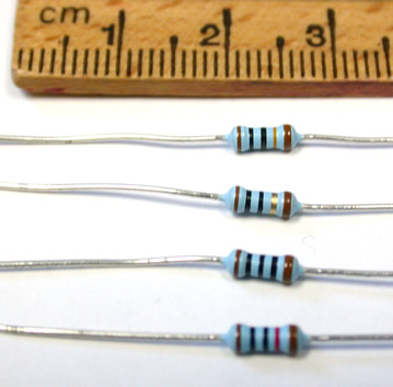
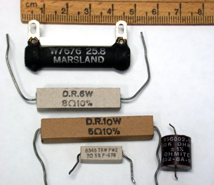
Leaded or through-hole resistors come in small, cylinder-like packages with axial wire leads (the wires are align with the main axis of the cylinder; parallel to main axis) or larger rectangular packages with axial or radial wire leads (the wires are aligned with the radius of the cylinder; perpendicular to main axis). Resistors come in in various compositions and consequently have different performance characteristics.
|
|
|
|
|
| [Click on image for better view] | |||
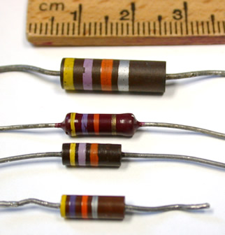
Depending on the physical size of the resistor, the value of the resistor is either printed on the resistor or encoded in a series of colour bands. The 4-band colour code is used for carbon composite, carbon film and metal oxide film resistors and is frequently referred to as the EIA [Electronic Industries Association] colour standard. The 5-band code is used for the more accurate metal film resistors. The 6-band colour code includes a temperature coefficient band.
| 4-band code | 5-band code | 6-band code | |
| Orientation | |||
| Value | bands 1, 2 | bands 1, 2, 3 | bands 1, 2, 3 |
| Multiplier | band 3 | band 4 | band 4 |
| Tolerance |
if band 4, ±5% or ±10% |
band 5 [less than ±5% ] |
band 5 [less than ±5% ] |
| Temperature Coefficient |
1,500 PPM/°C (carbon composition) | band 6 | |
| Failure Rate | band 5 on composition resistors (optional) | ||
| Terminal Type | wide band 5 on film resistors (optional) |
To read the bands correctly, the resistor must be oriented so that band 1 is at the left and bands are read from left to right. For 4-band colour coded resistors and larger 5-,6-band colour coded resistors, the colour bands will favour one end of the resistor. Orient the resistor so that the bands cluster to the left side of the resistor. For 5-,6-band colour coded resistors and some 4-band resistors, there may be a wider space between the multiplier and tolerance bands. Resistors with more bands or physically smaller resistors use band width instead of band spacing to indicate orientation; put the wide band to the right.
| Band Colour | Value Bands | Multiplier (ohms) ** | Tolerance | Temperature Coefficient | Failure Rate | |
| no band |
no band
|
± 20% | ||||
| Silver |
0.01
|
± 10% | ||||
| Gold |
0.1
|
± 5% | ||||
| Black |
0
|
1
|
||||
| Brown |
1
|
10
|
± 1% | 100 PPM | 1.0 | |
| Red |
2
|
100
|
± 2% | 50 PPM | 0.1 | |
| Orange |
3
|
1 k
|
15 PPM | 0.01 | ||
| Yellow |
4
|
10 k
|
25 PPM | 0.001 | ||
| Green |
5
|
100 k
|
± 0.5% | |||
| Blue |
6
|
1 M
|
± 0.25% | 10 PPM | ||
| Violet |
7
|
10 M
|
± 0.10% | 5 PPM | ||
| Gray |
8
|
0.01*
|
± 0.05% | 1 PPM | ||
| White |
9
|
0.1*
|
solderable terminal | |||
A resistor with only one black band is a zero Ohm resistor [NIC Component Corp., IRC]. A zero Ohm resistor is simply a jumper wire. This resistor exists to simplify the construction of a printed circuit board. Rather than using a special machine to place a single wire jumper, the regular resistor automatic placement system can be used with a zero Ohm resistor. Every resistor manufacturer will carry a zero Ohm resistor.
Resistors may also be labeled according to the military specifications (e.g. MIL-HDBK-217). Essentially, a part numbering system, it is used by both the military and commercial firms.
For older 4-band colour coded resistors, the body colour may be used as one of the four bands, as shown in RMA Resistor and Flexible Resistor Colour Codes [older variations on the 4-band system]. Newer 4-band colour coded resistors follow the EIA colour standard outlined above. Insulated resistors with axial leads are designated by a body of any colour except black. The usual colour is natural tan (beige) or brown for 4-band resistors. The usual colour is pale blue for 5-band resistors. Black bodies are used for noninsulated composition type resistors.
For newer resistors, the body colour may be used to identify a specific resistor type, as shown in NIC's radial leaded resistor products component appearance characteristics [PDF; NIC Components Corp., 1999; 1 page]. Some non-industry web pages state that blue resistors are non-flammable and white resistors are fusible. In fact, you can purchase flameproof resistors with a beige body, fusible resistors with a white body (IEC standard?), a red-brown body or a beige body, or you can order special purpose resistors and request a blue flameproof coating be added.
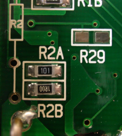
Surface mount (SMT) resistors come in tiny "chip-like" packages with a ceramic body and wire leads. Surface mount resistors have a series of numbers to denote the value of the resistor. The first n-1 digits are followed by the number of zeros indicated by the last number. For example, a surface mount resistor with code 1-0-5 would mean that the first two digits (1-0) would be followed by 5 zeros to give the value 1000000 Ohms or 1M Ohm.
If the number contains the letters R (1), K (1000), or M (1000000) in the series of numbers, interpret the letter as a decimal point and multiply as appropriate. For example, a code 3R5 would be interpreted as 3.5 Ohms, 3K5 would be interpreted as 3.5k Ohms, and 3M5 would be interpreted as 3.5M Ohms. This notation is also used on schematic diagrams when decimal points may be difficult to read.
The number may be followed by a letter to indicate the tolerance. The letters used are: M=±20%, K=±10%, J=±5%, G=±2%, F=±1%. Sometimes, the number of digits used in the number indicates the tolerance with 3 digits = ±5% and 4 digits = ±1%. However as chips get smaller, additional encoding may occur. For examples using standard coding and additional encoding based on chip size, see Component Marking Guideline [NIC Components Corp.].


![]()
Wilfrid Laurier University
© 2019 Wilfrid Laurier University